

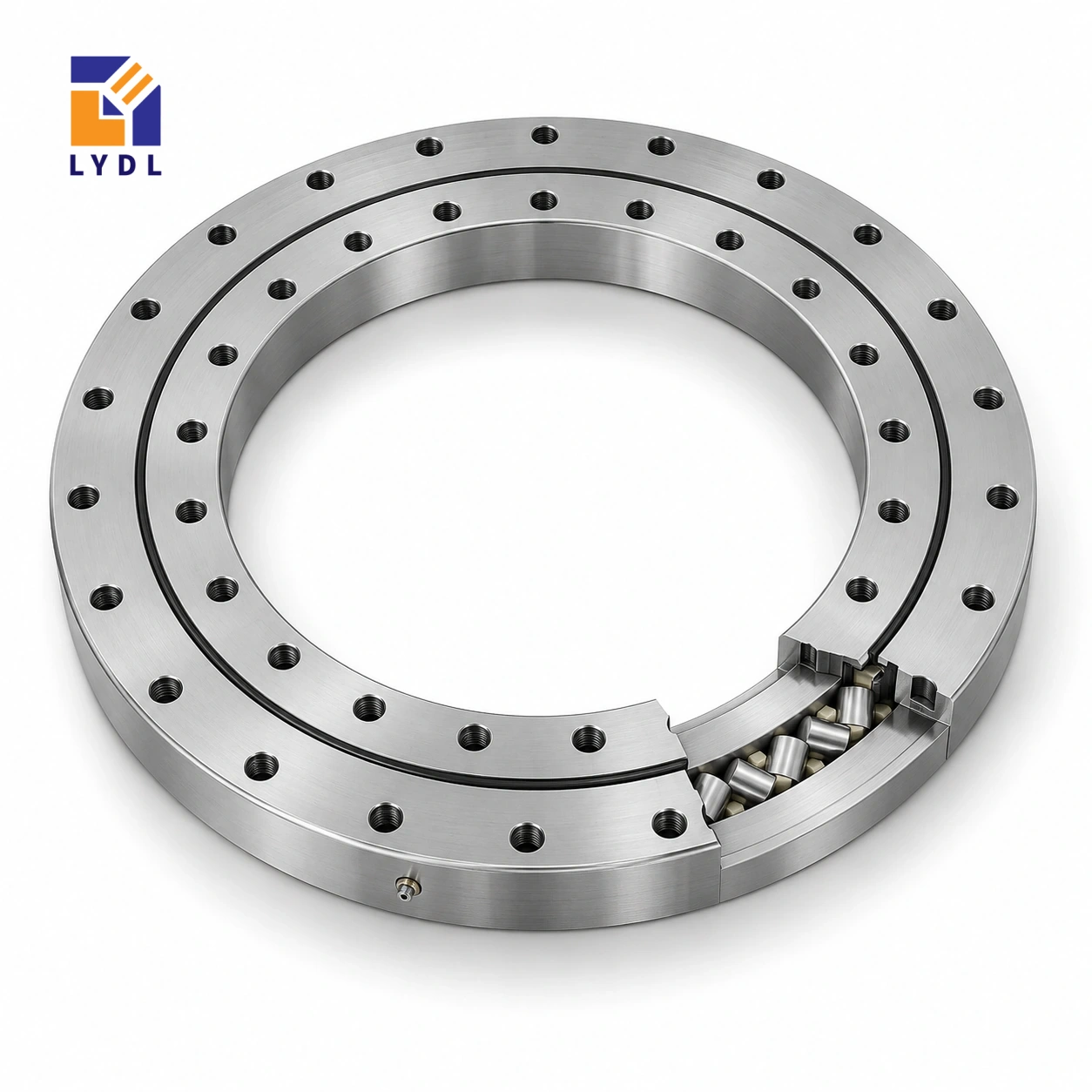
An XU120179 cross roller slewing bearing uses a 124.5 × 234 × 35 mm reference envelope. This ungeared design is useful to compare with ball-based rotary supports when the surrounding mechanism must be reviewed for running behaviour, stiffness and combined loading.
XU120179 original-reference geometry: Catalogue 404, pp. 90–93. LYDL supply follows its accepted drawing.
XU specification tables · Family technical reference
| Bore (mm) | Outside (mm) | Height H (mm) | Mass ≈ (kg) |
|---|---|---|---|
| 124.5 | 234 | 35 | 7 |
| Outer PCD La (mm) | Inner PCD Li (mm) | Outer holes na | Inner holes ni | Hole dB (mm) |
|---|---|---|---|---|
| 214 | 144.5 | 12 | 12 | 11 |
XU120179 and the VU140179 reference share the same basic envelope and fixing-circle values in the cited data. Their rolling-contact arrangements differ: XU uses crossed rollers, whereas VU belongs to the four-point contact ball family. A replacement decision therefore needs more than a dimensional overlay. Specify the permitted deflection, starting resistance and load spectrum, then check the supplied bearing execution against those needs. Matching envelopes can simplify a study without establishing interchangeability.
Use the 214 mm and 144.5 mm fixing circles as separate drawing features. Define the locating diameters and axial shoulders explicitly; the base reference and any centring execution should not be combined without confirmation.
Separate the angular movement of the ring from bending of the arm and bracket. A probe far from the support can show a large displacement even when the bearing contribution is small. Sketch the measurement location and define the applied probing force. Ask whether acceptance is judged unloaded, under a repeatable test force or during actual scanning.
That distinction helps determine which part needs redesign and prevents an expensive bearing change from being used to address flexibility elsewhere.
The XU120179 dimensions describe several different interfaces. Bore 124.5 mm and outside diameter 234 mm set the basic radial envelope; overall H = 35 mm sets the bearing's axial reference. Fixing circles La = 214 mm and Li = 144.5 mm locate the outer and inner attachment patterns, rather than the free opening or roller diameter. The reference lists 12 fixing positions on each ring. A circle and a count do not fully describe a hole: seat details, thread engagement and angular orientation still belong on the accepted drawing. Approximate mass 7 kg is a component property, not an approved payload. Reading these fields separately helps prevent a correct catalogue number being transferred to the wrong feature of a mating plate.
The matching basic envelope of XU120179 and VU140179 makes them useful candidates for an interface study. Start by identifying which existing machine features must remain: the centre opening, support surfaces, attachment patterns and working height. Record those constraints on the comparison drawing. Then list the required operating behaviour separately, including loaded angular displacement, movement at reversal and the duty of the rotary stage.
The two contact arrangements should be compared through the actual proposed executions. A shared envelope does not establish the same internal condition, sealing details or performance. Ask for the information relevant to the stated requirement rather than treating a roller design as an automatic improvement. If the original machine has a known concern, describe where it is observed and under what load. This gives a basis for deciding whether the bearing proposal, supporting structure or transmission deserves attention. The dimensional match narrows a search; the accepted drawing and application review establish whether the proposed arrangement is useful.
Draw the arm from its attachment on the rotating plate to the actual measuring point. Identify the direction and position of the probing or process force. Angular movement at the support and bending of the arm can both contribute to displacement at that point. A long arm can amplify the observed effect of either contribution.
Define a repeatable measurement condition for the equipment. State whether the reading is taken under a representative contact force, during scanning or after the arm has settled at a station. Record how the workpiece and fixture are reseated between tests. If several arm lengths or probe heads are permitted, identify the configuration that bounds the requirement. These descriptions are more actionable than a general precision label. They help the equipment engineer separate the system error budget and allow LYDL to review the supplied component against a defined task. Any acceptance requirement for the bearing itself still needs its own drawing features and test condition, rather than being copied directly from a remote probe reading.
Use the 214 mm outer and 144.5 mm inner fixing circles in the reference layout, keeping both distinct from the 124.5 mm bore. Establish the centring and shoulder details from the accepted execution before machining. Where a previous web table uses a conflicting auxiliary entry, a consistent source drawing is needed instead of combining whichever dimensions appear convenient.
Check the actual support annuli and local plate sections beneath the connections. A cutout for a cable or probe service should be included in the same structural drawing used for review. Identify the mounting-face datum and the method used to inspect it after machining. The drive bracket should also appear, because a gearless ring still receives reactions from the separately designed transmission. Plan the screw-tool paths around the arm and central services. An assembly instruction that identifies the order of these parts can prevent an otherwise compatible bearing from being installed with inaccessible attachment points.
The enquiry should distinguish reference geometry from the requested LYDL supply. Identify the complete model, required quantity, mating drawing revision and intended equipment duty. State which running or dimensional features will be assessed and how the result is to be interpreted. Do not request a numerical accuracy or preload value solely because it appears in another manufacturer's reference information.
At delivery, retain identification of the actual offered execution and the agreed inspection record. Protect locating faces from loose fixture hardware while the bearing is stored or transported to assembly. During commissioning, compare the completed measuring stage under the documented arm configuration. Keep that baseline with the component and machine drawings, including any adapter or changed drive setting. A later investigation can then compare like conditions instead of attributing every change to the bearing. The main photograph on this page illustrates the series arrangement; the supplied appearance and acceptance features should be confirmed for the ordered model.
For an initial dimensional shortlist, place XU120179 (124.5 × 234 × 35 mm) beside XU120222 (140 × 300 × 36 mm) and XU080149 (101.6 × 196.85 × 22.22 mm). These nearby requested references provide a useful envelope comparison, not a sequence of increasing approved load ratings. Compare their actual bolt circles and support faces before deciding which deserves a detailed drawing review. A smaller bore can conflict with the service route, while a different outside diameter changes the available backing annulus. Retain the complete model in every enquiry so a proposal is tied to the intended row. Only the accepted execution and application assessment can resolve the final choice.
A fixture carrying an offset measuring arm is a representative study. Treat arm overhang and contact-probe forces as inputs, and assess the complete bracket stiffness alongside the bearing arrangement.

Request the agreed datum-based dimensional check and specify how rotation resistance will be assessed. A useful inspection record identifies the actual supplied execution rather than a generic family.

The nominal reference is 124.5 mm bore, 234 mm outside diameter and 35 mm overall height.
The basic dimensions align in the reference tables, but crossed rollers and four-point balls have different behaviour. Confirm the complete application and execution.
The cited catalogue lists 144.5 mm. Use that source with the approved drawing instead of copying the inconsistent rounded series row.
Describe the measuring location, applied force and permitted displacement. A general request for high precision does not define the acceptance test.
The designer still selects an external drive arrangement. Include its reaction forces and mounting bracket in the bearing review.
Roller interface comparison: XSU series. Ball-contact option: VU range.
For XU120179, include the comparison drawing and the allowable measuring-arm displacement under load.