

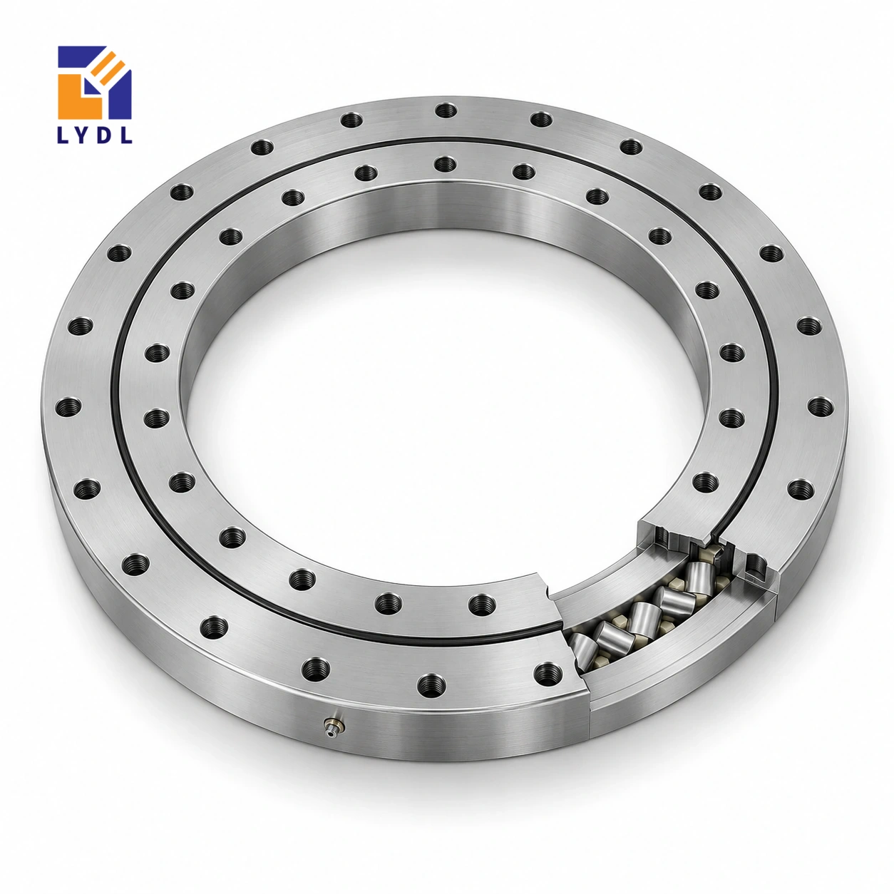
XU080149 is a gearless crossed roller reference with a 101.6 mm bore and a 196.85 mm outside diameter. Its 22.22 mm axial envelope and sixteen-position fixing patterns distinguish it from nearby XU references that may appear similar in a catalogue photograph.
XU080149 original-reference geometry: Catalogue 404, pp. 90–93. LYDL supply follows its accepted drawing.
XU specification tables · Family technical reference
| Bore (mm) | Outside (mm) | Height H (mm) | Mass ≈ (kg) |
|---|---|---|---|
| 101.6 | 196.85 | 22.22 | 3.6 |
| Outer PCD La (mm) | Inner PCD Li (mm) | Outer holes na | Inner holes ni | Hole dB (mm) |
|---|---|---|---|---|
| 177.8 | 115.8 | 16 | 16 | 6.9 |
The 177.8 mm outer circle and 115.8 mm inner circle each carry sixteen holes. Lay out the mating plate around those positions before adding slots for adjustment or cable clips. A dense connection can leave less freedom for additional machining, particularly near the inner pilot. Confirm local material thickness beneath screw seats and maintain access for the tightening tool. Do not infer a higher system load limit simply from the number of fasteners.
Preserve the 101.6 mm and 196.85 mm locating-envelope values in the manufacturing drawing. Check screw length against both plate thickness and permitted engagement so tips cannot foul the moving assembly.
Place the return-current attachment on the workpiece or fixture according to the equipment electrical design, with a route that avoids relying on rolling contacts. A dedicated connection also needs mechanical freedom through the intended travel. Check whether its cable pulls on the rotating head at either extreme. Record that cable reaction as an equipment load when it is significant.
Protect exposed screw seats from spatter, but preserve access so routine fixture changes do not require disturbing the bearing seating.
The XU080149 dimensions describe several different interfaces. Bore 101.6 mm and outside diameter 196.85 mm set the basic radial envelope; overall H = 22.22 mm sets the bearing's axial reference. Fixing circles La = 177.8 mm and Li = 115.8 mm locate the outer and inner attachment patterns, rather than the free opening or roller diameter. The reference lists 16 fixing positions on each ring. A circle and a count do not fully describe a hole: seat details, thread engagement and angular orientation still belong on the accepted drawing. Approximate mass 3.6 kg is a component property, not an approved payload. Reading these fields separately helps prevent a correct catalogue number being transferred to the wrong feature of a mating plate.
Lay out both fixing patterns before adding workholding slots, dowels or service brackets. The 177.8 mm and 115.8 mm circles each have sixteen positions, but the surrounding plate also needs enough material to support screw seats and transmit forces. Show the actual plate boundary and any pockets around those regions. A drawing of the hole centres alone cannot demonstrate that the complete flange is suitable.
Define how the mating plates are located concentrically and how their angular relationship is established. If an adjustable fixture is installed above the bearing, keep its adjustment features separate from the bearing connection. Check that the chosen tools reach each fastener after the fixture is present. Removal access also matters: a screw may be tighten-able with a special driver while still lacking the clearance needed for withdrawal. Resolve that sequence while the layout is flexible. The reference pattern provides a useful connection geometry, but hole quantity should not be used as a substitute for an assessment of the supporting structure or operating forces.
A welding head needs mechanical, electrical and contamination arrangements that work together. Show the workpiece clamp and the intended electrical return in the same equipment layout. The return path should be defined by the machine electrical design, with enough freedom to accommodate the approved rotation. A heavy return cable can exert a reaction that changes with angular position, so include its restraint and routing in the load description when relevant.
Review the direction from which spatter and process debris can reach the ring and mounting features. Covers should protect the intended region without obstructing screw access or trapping material against a seal. State the cleaning method and the environment expected during idle periods. These details help establish what the offered sealing and lubrication configuration must address. The bearing dimensions do not certify suitability for a particular welding exposure. A representative application image shows a possible equipment task; it should not be read as evidence that this exact model has been tested in a specific welding process.
Mark the workpiece centre of gravity through its allowed orientations. A part that is balanced about one fixture axis may still be offset from the bearing plane. Include the height and direction of clamp forces, as well as any external contact from tooling. Describe whether those forces act while the head rotates, while it holds position or during loading and unloading.
For movement, provide the assembly mass distribution and the planned acceleration or reversing sequence. Include the faceplate, clamps and attached drive hardware, not just the part being welded. A short emergency stop can differ from the normal programmed return, so identify it separately if it belongs to the approved operating cases. These inputs define the review more usefully than an unspecified request for heavy-duty performance. The resulting proposal should explain the offered execution and applicable limits for the stated task. Do not infer those limits from the shallow 22.22 mm envelope or from the sixteen-position ring connections.
Identify the surfaces that establish the faceplate working level and the location of the workpiece. Agree the bearing dimensions and functional observations required at receiving, with the support condition stated. Separately define how the complete head is checked after it is bolted to the machine. An unloaded component reading and a loaded fixture measurement are different records.
For commissioning, use a named fixture configuration and retain the corresponding clamp and cable arrangement. Record any interference check around guards and any change in rotation behaviour during assembly. Keep the model identification and supply drawing linked to that equipment record. During shipment, separate loose bolts and welding accessories from the machined bearing faces. A retained spacer or adapter should also be identified, because a later spare order may otherwise reproduce only part of the approved arrangement. This approach makes both purchasing and maintenance more precise without adding unsupported claims about precision class, preload or service life to the product page.
For an initial dimensional shortlist, place XU080149 (101.6 × 196.85 × 22.22 mm) beside XU120179 (124.5 × 234 × 35 mm) and XU060111 (76.2 × 145.79 × 15.87 mm). These nearby requested references provide a useful envelope comparison, not a sequence of increasing approved load ratings. Compare their actual bolt circles and support faces before deciding which deserves a detailed drawing review. A smaller bore can conflict with the service route, while a different outside diameter changes the available backing annulus. Retain the complete model in every enquiry so a proposal is tied to the intended row. Only the accepted execution and application assessment can resolve the final choice.
For a compact welding-positioner head, examine torch access and the return-current path as well as mechanical loads. The bearing should not be assumed to provide the designed electrical return connection.

Discuss seat-face measurements and rotation checks after the delivery configuration is agreed. During packing, shield the closely spaced fixing features from loose screws or other metal parts.

Sixteen per ring are listed, on 177.8 mm and 115.8 mm circles. Compare both patterns with your machine plate.
The catalogue reference height is 22.22 mm. Extra covers, spacers or screw projections must be considered separately.
It is a nominal reference dimension. Mating tolerances and pilot details require the accepted LYDL drawing.
Do not use it as an assumed electrical return path. Design and verify a dedicated return arrangement for the positioner.
No. Screw properties, plate stiffness, load direction and raceway capacity all influence the approved operating envelope.
Roller interface comparison: XSU series. Ball-contact option: VU range.
Send the proposed head plate, fastening arrangement and welding-current return design for XU080149 review.