

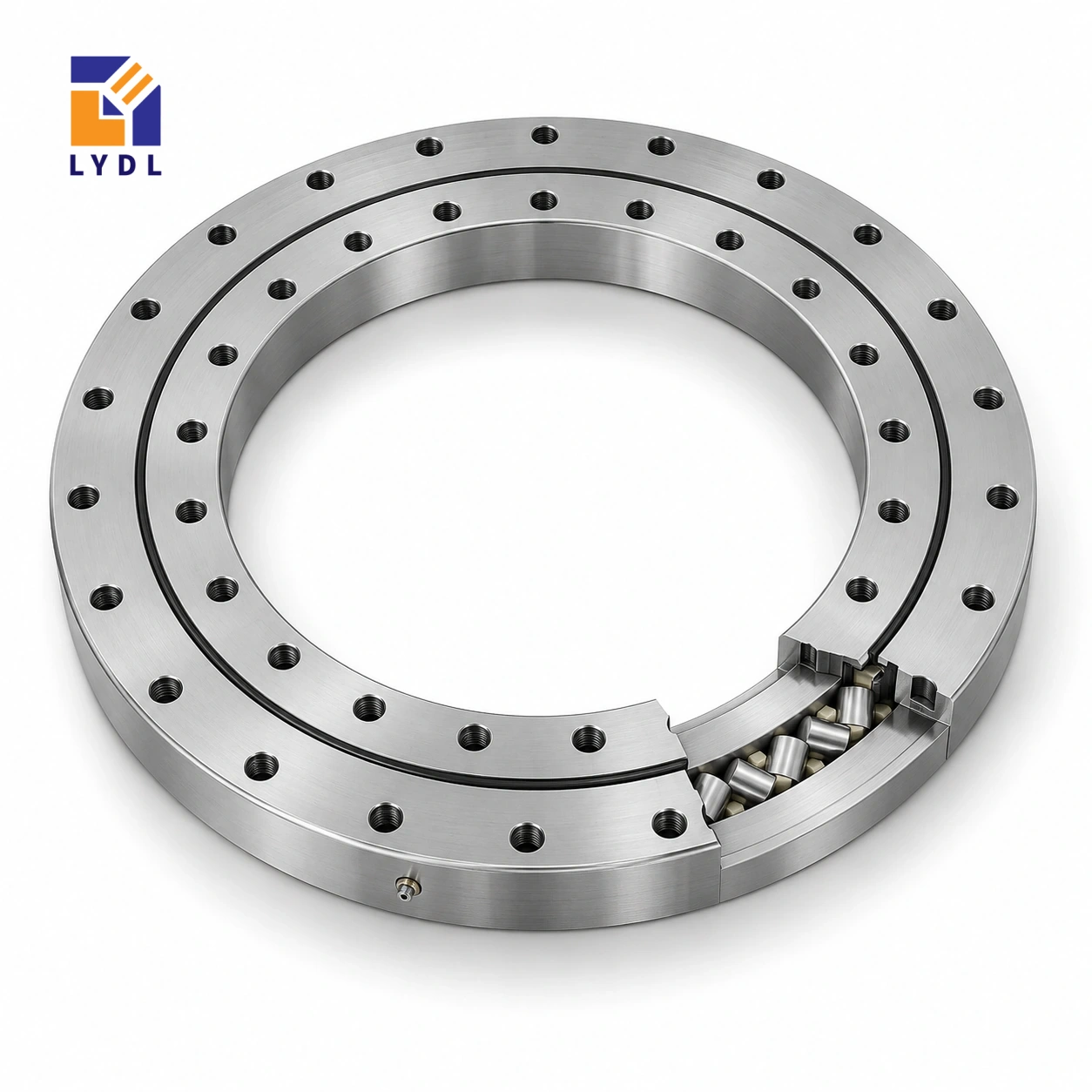
An XU080120 cross roller slewing bearing provides a gearless reference arrangement around a 69 mm bore. Its 170 mm outside diameter and 30 mm height should be considered together with the mounting details, particularly when replacing a compact rotary support rather than designing a new housing.
XU080120 original-reference geometry: Catalogue 404, pp. 90–93. LYDL supply follows its accepted drawing.
XU specification tables · Family technical reference
| Bore (mm) | Outside (mm) | Height H (mm) | Mass ≈ (kg) |
|---|---|---|---|
| 69 | 170 | 30 | 4 |
| Outer PCD La (mm) | Inner PCD Li (mm) | Outer holes na | Inner holes ni | Hole dB (mm) |
|---|---|---|---|---|
| 148 | 90 | 6 | 6 | 9 |
The mounting circles are 148 mm outside and 90 mm inside, with six fixing positions on each ring. Those numbers describe the connection to the machine; they are not the clear opening or the rolling-element diameter. For a retrofit, measure the existing flange and locate its pilot before comparing catalogue numbers. An adapter may solve a bolt-circle mismatch while also changing the axial stack and the distance between the payload and bearing plane.
Check screw-head seats and engagement on both sides. Establish a tightening sequence for the complete flange assembly, then measure rotation resistance after attachment so a distorted support is detected before the motor is commissioned.
If the turret already exists, record its operating height before dismantling the old support. Check how an adapter affects gripper engagement with the next station and whether adjustment remains available. A successful bolt-pattern conversion can still put the product at the wrong working level. Identify the surfaces that should locate the adapter and those intended only for clamping.
Keep those functions explicit so assembly does not depend on screw clearance to centre the rotating nest.
The XU080120 dimensions describe several different interfaces. Bore 69 mm and outside diameter 170 mm set the basic radial envelope; overall H = 30 mm sets the bearing's axial reference. Fixing circles La = 148 mm and Li = 90 mm locate the outer and inner attachment patterns, rather than the free opening or roller diameter. The reference lists 6 fixing positions on each ring. A circle and a count do not fully describe a hole: seat details, thread engagement and angular orientation still belong on the accepted drawing. Approximate mass 4 kg is a component property, not an approved payload. Reading these fields separately helps prevent a correct catalogue number being transferred to the wrong feature of a mating plate.
A changeover turret normally interfaces with more than its bearing. Product guides, grippers, sensors and the next station may all rely on a fixed presentation height. Mark those relationships on the equipment drawing before considering an adapter. Place the 30 mm reference bearing envelope in the axial stack and add the actual plate sections, locating shoulders and fastener projections. Identify which features may move and which are fixed machine constraints.
If an adapter connects an existing turret to a different fixing pattern, it needs its own locating method on both sides. Determine how concentricity is established during assembly and how the adapter is restrained after alignment. Check whether the added thickness moves the drive out of its intended plane or changes tool access. A conversion that accommodates the six-position rings may still require revised guarding or a different service sequence. Document these consequences while reviewing the layout, so the bearing request is linked to a coherent machine modification rather than an isolated envelope match.
Map a complete turret cycle from loading through release. Indicate when each gripper closes, when the product is supported by another machine element, and when the turret alone carries it. A transfer contact can introduce a lateral force even if the product weight is modest. Describe that contact at its actual height and distance from the rotation axis.
Then identify the mass distribution that moves during indexing. Include empty grippers and any equipment attached to the turret, not only the products. State the acceleration and stopping pattern and whether reversal occurs in normal operation. If the drive is connected through a belt, arm or coupling, draw how its reaction reaches the supporting plate. The bearing reference contains no integral teeth, so this transmission is part of the equipment design. Keeping the handling forces and motion requirements distinct helps determine which operating state governs each part of the proposed assembly.
The 69 mm bore and 90 mm inner fixing circle describe different parts of the interface. Show a central rotary union or service bundle in its fully assembled condition, including connectors. Check the path of the tightening tool to every inner position. A screw that is easy to reach before the union is fitted may become inaccessible afterwards.
Decide whether the union is removed independently of the turret and whether its connections can be disconnected without pulling on the bearing or its seals. Include the withdrawal space required by the union body, not just the operating clearance around its shaft. Review the outer screw access with guards in place and in the documented maintenance configuration. This allows the assembly sequence to be written before parts are manufactured. For a replacement enquiry, photographs can help explain access, but dimensioned sections are needed to define the locating and connection geometry.
Record the condition of the seating faces before the ring is attached. Check for debris, burrs and contact with unintended neighbouring features. Use the accepted screw specification and assembly procedure for the offered execution. Compare rotation behaviour at defined stages, including after the upper turret and drive are installed, so an unexpected change can be associated with a specific assembly step.
Verify product presentation at the actual working station under the agreed operating condition. A successful unloaded rotation does not establish alignment with downstream grippers or guides. Note which tooling configuration was used and how the station was loaded. Retain the bearing model, supply drawing, adapter revision and commissioning observations together. These records are especially useful when several interchangeable turret plates exist. They give maintenance staff a known arrangement to reproduce and provide LYDL with concrete evidence if a later operating concern requires review. The enquiry should also identify the required quantity and whether the order is a sample, a planned spare or a conversion batch.
For an initial dimensional shortlist, place XU080120 (69 × 170 × 30 mm) beside XU060111 (76.2 × 145.79 × 15.87 mm) and XU060094 (57 × 140 × 26 mm). These nearby requested references provide a useful envelope comparison, not a sequence of increasing approved load ratings. Compare their actual bolt circles and support faces before deciding which deserves a detailed drawing review. A smaller bore can conflict with the service route, while a different outside diameter changes the available backing annulus. Retain the complete model in every enquiry so a proposal is tied to the intended row. Only the accepted execution and application assessment can resolve the final choice.
A packaging-machine changeover turret is one possible design study. Assess the gripper offset, intermittent acceleration and available cable route before deciding whether the six-position connection suits the turret plate.

Record the delivered ring identification and the flange datum used for inspection. Specify separate protection for screw seats and sealing edges during transport.

The bore reference is 69 mm. The 90 mm value belongs to the inner fixing circle, so the two dimensions serve different purposes.
Six positions are listed per ring, on 148 mm and 90 mm circles. Verify the complete hole and screw-seat geometry.
Thirty millimetres describes the bearing envelope only. Your adapter plate, fastener projections and mounting shoulders need additional space.
A stiffer plate may help support conditions but also shifts the payload. Recalculate the resulting moment and examine the complete structure.
Compare free and mounted rotation behaviour, inspect seating contact, and resolve unexpected resistance before applying operating loads.
Roller interface comparison: XSU series. Ball-contact option: VU range.
Include the old support drawing and the proposed adapter thickness when requesting XU080120 replacement review.