

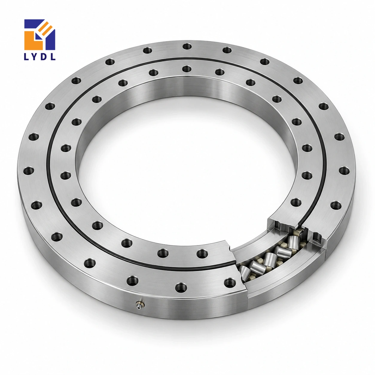
The XU060111 cross roller slewing bearing reference has an inch-related envelope expressed here in millimetres: 76.2 mm bore, 145.79 mm outside diameter and 15.87 mm height. Its shallow profile makes exact interface dimensions especially important during a legacy-equipment retrofit.
XU060111 original-reference geometry: Catalogue 404, pp. 90–93. LYDL supply follows its accepted drawing.
XU specification tables · Family technical reference
| Bore (mm) | Outside (mm) | Height H (mm) | Mass ≈ (kg) |
|---|---|---|---|
| 76.2 | 145.79 | 15.87 | 1.2 |
| Outer PCD La (mm) | Inner PCD Li (mm) | Outer holes na | Inner holes ni | Hole dB (mm) |
|---|---|---|---|---|
| 133.1 | 88.9 | 8 | 8 | 6.9 |
Rounding this reference to a convenient metric housing size can conceal an incompatible pilot or screw pattern. Use the existing machine drawing to establish which dimensions locate the bearing and which merely provide clearance. The fixing circles are 133.1 mm and 88.9 mm, with eight holes on each ring. Check the complete ordering designation and drawing revision if an old purchase record adds a suffix; a base model alone does not settle every execution detail.
Map the seal-cover arrangement and support faces before defining the axial stack. A shallow ring can be distorted by an uneven backing plate, so examine the flange contact pattern and the assembly method together.
Retain the original unit system in the source record and show any converted dimensions explicitly on the new drawing. A decimal that looks unnecessarily precise may originate from an inch-based feature. Do not mix a converted nominal with a tolerance copied from a different metric component. Identify the dated machine drawing and the supplied bearing revision together, especially when previous repairs introduced spacers or a replacement cover that was never incorporated into the original equipment documentation.
The XU060111 dimensions describe several different interfaces. Bore 76.2 mm and outside diameter 145.79 mm set the basic radial envelope; overall H = 15.87 mm sets the bearing's axial reference. Fixing circles La = 133.1 mm and Li = 88.9 mm locate the outer and inner attachment patterns, rather than the free opening or roller diameter. The reference lists 8 fixing positions on each ring. A circle and a count do not fully describe a hole: seat details, thread engagement and angular orientation still belong on the accepted drawing. Approximate mass 1.2 kg is a component property, not an approved payload. Reading these fields separately helps prevent a correct catalogue number being transferred to the wrong feature of a mating plate.
The decimals in this reference should remain visible throughout the replacement study. A 76.2 mm bore is a different nominal feature from a rounded 76 mm opening, and the same discipline applies to the outside diameter and fixing circles. Start with the original machine drawing and identify whether its source units were inches or millimetres. Preserve that record when producing a new drawing so later inspection does not depend on an undocumented conversion.
Make a feature list that separates the bearing envelope from the mating pilots, screw seats and covers. An accessible diameter measured on an assembled stage may belong to a cover rather than the bearing ring. Record which component was measured and whether it was removed from the equipment. If an old part has no complete marking, compare several independent features before accepting a model identification. These observations support the enquiry, while the exact offered execution still needs a consistent drawing. They are especially useful on older machines that have accumulated unrecorded repairs or locally manufactured spacers.
A shallow bearing package leaves limited scope for an unnoticed axial change. Show the mounting faces and the equipment working datum on one section, then place the bearing, covers and any adapters between them. Record whether either surrounding component also locates a seal or limits the available travel. A replacement that fits between two plates can still alter the relationship between the moving stage and its measurement system.
Check screw projections and the space needed for the assembly tools. The eight-position reference patterns should be laid out from the correct centres, not adjusted to compensate for an uncertain pilot. Inspect the supporting surfaces in the condition in which they will be assembled. If a plate is thin enough to change shape when clamped during machining, agree how that condition is represented in the inspection record. The objective is a defined supported assembly, rather than an assumption that fastening the shallow ring will bring mismatched components into alignment. Any added shim or adapter needs its own location and retention method.
An optical alignment mechanism can be judged at several locations: the rotary axis, a fixture surface, a target on the workpiece or the resulting optical signal. State which result matters to the equipment and how it is measured. The bearing contributes to the arrangement, but a reading at a distant target also includes bracket bending, fixture seating and adjustment behaviour.
Use a consistent target and describe whether the stage is tested unloaded or under a stated representative force. Note the approach direction and whether the drive reverses before the measurement. If the concern is repeatability, include how the target or workpiece is reseated between cycles. If it is loaded displacement, identify the force location and the permitted equipment response. These are specification inputs, not properties inferred from the XU designation. Sharing this information with LYDL helps connect the offered component execution to a meaningful review. It also prevents the nominal dimensions from being presented as a guarantee for the accuracy of the complete optical system.
Retain the complete marking from the removed component, including any additional letters on an old purchase record. Do not discard a suffix because the basic envelope appears familiar. Send the drawing, photographs of identification and the measured interface list together, making clear which information came from the machine and which came from an original reference source.
For the proposal, identify the supplied LYDL designation, drawing revision and acceptance features. Ask which details require confirmation before the mating parts are manufactured. Preserve any approved deviations on the equipment record rather than relying on a verbal description of a close fit. At receiving, compare the delivered identification with that record and keep the protective package until the assembly location is prepared. Record the stage configuration used at commissioning, including adapters introduced during the repair. A future spare can then be requested for the actual approved arrangement. The source catalogue supports the reference comparison; it does not replace the supplied drawing or document the condition of the legacy equipment.
For an initial dimensional shortlist, place XU060111 (76.2 × 145.79 × 15.87 mm) beside XU080120 (69 × 170 × 30 mm) and XU060094 (57 × 140 × 26 mm). These nearby requested references provide a useful envelope comparison, not a sequence of increasing approved load ratings. Compare their actual bolt circles and support faces before deciding which deserves a detailed drawing review. A smaller bore can conflict with the service route, while a different outside diameter changes the available backing annulus. Retain the complete model in every enquiry so a proposal is tied to the intended row. Only the accepted execution and application assessment can resolve the final choice.
An older optical alignment stage is a possible comparison case. Its adjustment mechanism, measurement datum and drive bracket should be evaluated as one assembly before assigning an accuracy requirement to the bearing.

Request measurements in the agreed units without rounding away the interface decimals. Protect the thin axial package from bending loads when it is removed from its shipping support.

The cited nominal bore is 76.2 mm. Keep the decimal value when reviewing the existing shaft or pilot.
The reference interface uses 133.1 mm and 88.9 mm circles. A metric redraw must preserve their intended geometry rather than round them.
The 15.87 mm height is one packaging constraint. Plate stiffness, sealing details and permissible loads also need review.
Retain it in the enquiry and compare its drawing. This page identifies the requested base model without declaring all suffix executions equivalent.
Provide the measurement axis, required running behaviour, existing mating parts and full adjustment travel, together with the original installation drawing.
Roller interface comparison: XSU series. Ball-contact option: VU range.
Attach the legacy drawing and complete nameplate suffix for XU060111 dimensional and execution review.