

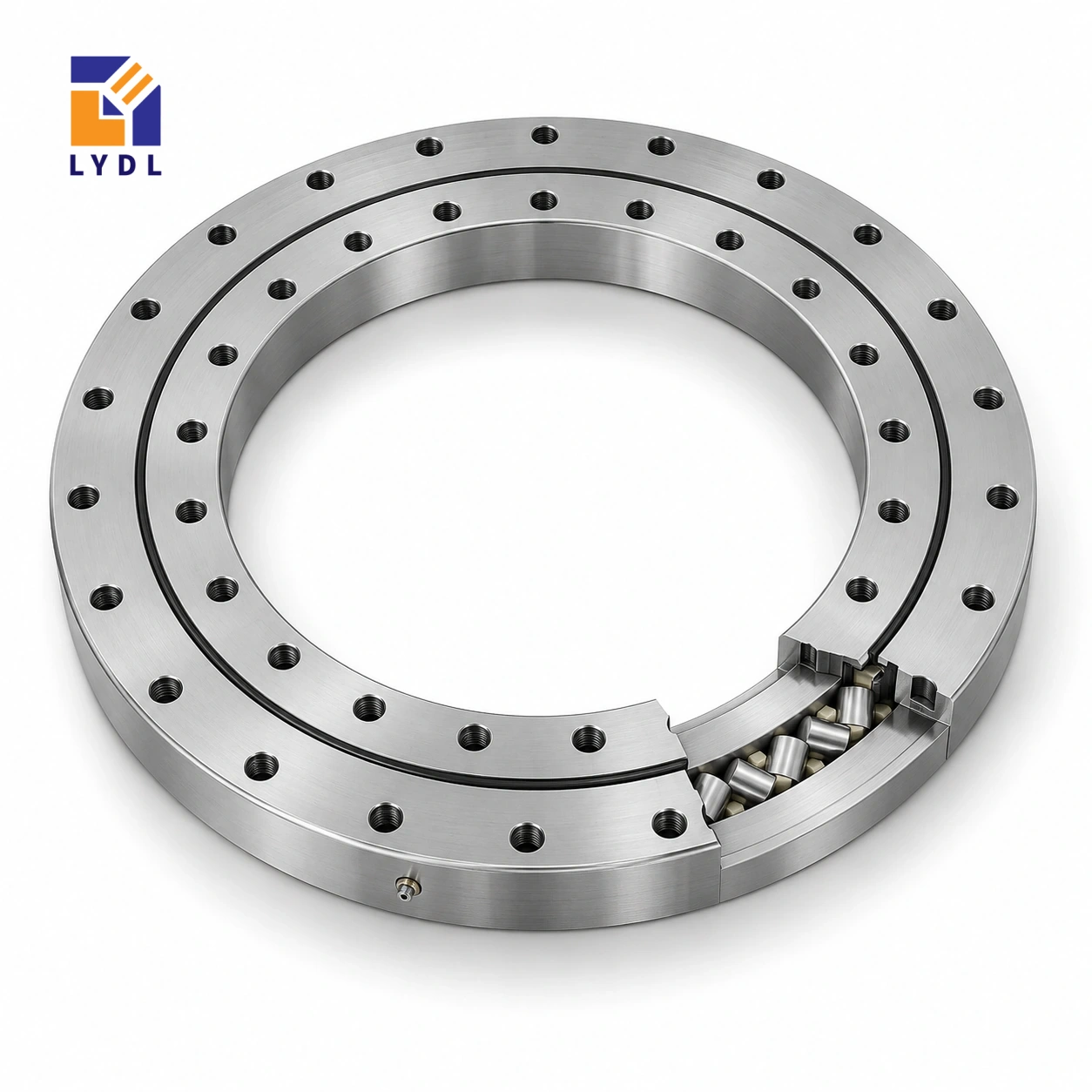
XU060094 is an ungeared cross roller slewing bearing reference measuring 57 × 140 × 26 mm. It is worth examining where a compact mechanism needs a central service passage and a bolted rotary interface, with suitability established from the actual loads and support geometry.
XU060094 original-reference geometry: Catalogue 404, pp. 90–93. LYDL supply follows its accepted drawing.
XU specification tables · Family technical reference
| Bore (mm) | Outside (mm) | Height H (mm) | Mass ≈ (kg) |
|---|---|---|---|
| 57 | 140 | 26 | 2.4 |
| Outer PCD La (mm) | Inner PCD Li (mm) | Outer holes na | Inner holes ni | Hole dB (mm) |
|---|---|---|---|---|
| 120 | 70 | 6 | 6 | 9 |
A 57 mm centre opening can be a useful starting point for a pneumatic tube, cable bundle or small rotary union. Check the outside envelope of those services through their full motion, including connectors and minimum bend radii. The bearing should carry the mechanism loads through its rings and fasteners; an unsupported hose bundle can add an unplanned side force. Define how the services are restrained on each side of the rotating joint.
The reference fixing circles are 120 mm and 70 mm. With six holes per ring, access around a central union deserves attention. Confirm the 9 mm hole details and counterbores against the drawing before machining.
Measure the assembled fitting as well as the hose diameter when studying the centre passage. A connector may need more space during installation than it occupies once tightened. Determine whether replacement can be carried out from above, below or through a removable cover. Include that route in the machine drawing.
Restricting access after the bearing has been selected can turn routine seal or hose work into removal of the complete rotating fixture.
The XU060094 dimensions describe several different interfaces. Bore 57 mm and outside diameter 140 mm set the basic radial envelope; overall H = 26 mm sets the bearing's axial reference. Fixing circles La = 120 mm and Li = 70 mm locate the outer and inner attachment patterns, rather than the free opening or roller diameter. The reference lists 6 fixing positions on each ring. A circle and a count do not fully describe a hole: seat details, thread engagement and angular orientation still belong on the accepted drawing. Approximate mass 2.4 kg is a component property, not an approved payload. Reading these fields separately helps prevent a correct catalogue number being transferred to the wrong feature of a mating plate.
A central service passage needs to accommodate installation and movement as well as the nominal hose diameter. Start with the largest fitting, connector or union that must pass through the opening. Include the space required to turn a threaded connection and the bend permitted by the chosen line. The 57 mm reference bore is an envelope input; the finished support can contain pilots and hardware that reduce the available passage.
Define which services rotate and which remain fixed. Show their restraints on both sides of the joint so hose reaction is not transferred through an improvised contact with a rotating ring. Check the line positions at the travel extremes and during maintenance. If a connector must be removed before the fixture can be lifted, include that step in the equipment instructions. A serviceable layout allows those operations to be completed without disturbing an otherwise correct bearing connection. This is a useful design distinction for a compact pneumatic fixture where additional sensors often consume the last available clearance.
Draw the workpiece against its locating stops and identify every actuator that applies force. A pneumatic cylinder pressing vertically and a side clamp do not create the same reaction at the rotary support. Show their application heights, lever arms and the order in which they operate. If a misloaded part can cause the clamp to bear against an unintended surface, describe the approved recovery procedure and any relevant additional loading.
During rotation, identify whether the clamps remain pressurised and whether pressure lines change their bending state. Include the nest and actuator bodies in the moving assembly. The appropriate selection information is a set of equipment conditions, not a force guessed from the bearing model number. State which positions are permitted by the machine controls and which are excluded. This helps keep the proposal tied to the intended duty and gives a clear basis for reviewing subsequent changes to the clamp layout or workpiece size.
Keep the 120 mm and 70 mm fixing circles on a common coordinate system with the part-location datum. The supporting plates should show the complete hole form, screw seats and centring features from the accepted bearing drawing. A hole-diameter entry alone cannot define a counterbore or the permitted screw-head projection.
Review local plate material around the inner connection, particularly if a rotary union occupies the centre. Avoid allowing a service cutout or adjustment slot to interrupt the intended support without including it in the structural review. Establish how both mating surfaces are inspected after their final machining operations. If a plate is held in a fixture during inspection, identify that condition when it affects the reading. At assembly, resolve an unexpected pilot fit before tightening. The fasteners should secure the designed seating arrangement rather than force uncertain mating features into alignment. These checks connect the reference dimensions to a reproducible manufactured interface.
Identify the measurements needed to accept the purchased ring separately from the checks needed to commission the complete station. Receiving inspection may concern identity and agreed dimensions. Machine acceptance can also involve nest presentation, clamp operation and rotation under the representative service arrangement. State the condition for each result so the records remain comparable.
Discuss the actual cleaning and contamination environment when defining the offered sealing and lubrication execution. Nearby compressed-air equipment does not establish a clean bearing environment, especially if the fixture handles debris-producing parts. Specify the intended storage period and keep fittings or cylinders from rubbing against the ring in the shipment. Preserve the model and drawing reference on the receiving record after unpacking. For a future spare, retain the union and clamp revisions alongside the bearing information. An enquiry that includes these details, the cycle description and destination supports a clearer supply proposal than a request based only on bore size.
For an initial dimensional shortlist, place XU060094 (57 × 140 × 26 mm) beside XU080120 (69 × 170 × 30 mm) and XU050077 (40 × 112 × 22 mm). These nearby requested references provide a useful envelope comparison, not a sequence of increasing approved load ratings. Compare their actual bolt circles and support faces before deciding which deserves a detailed drawing review. A smaller bore can conflict with the service route, while a different outside diameter changes the available backing annulus. Retain the complete model in every enquiry so a proposal is tied to the intended row. Only the accepted execution and application assessment can resolve the final choice.
A pneumatic assembly fixture could use this size as its rotary station support. Map clamp forces into the fixture plate and include the force generated when the workpiece is pressed into position.

Ask for dimensional identification tied to the agreed revision. Protect the bore against impact from fittings packed in the same shipment, and keep the bearing closed until installation.

The nominal bore is 57 mm. Check the fitting, connector and moving-service envelopes before treating the full opening as usable clearance.
The reference specifies six holes on each ring, rather than six shared between the complete assembly.
They identify the outer and inner fixing circles. They do not describe the bearing outside diameter or centre opening.
They need their own routing and strain relief. Include their bending reaction and avoid contact with the rotating ring.
Describe force magnitude, application point and support reaction. A short pressing event may govern selection even if most of the cycle is lightly loaded.
Roller interface comparison: XSU series. Ball-contact option: VU range.
Provide a section through the rotary union and describe the clamp-force direction for an XU060094 quotation.