

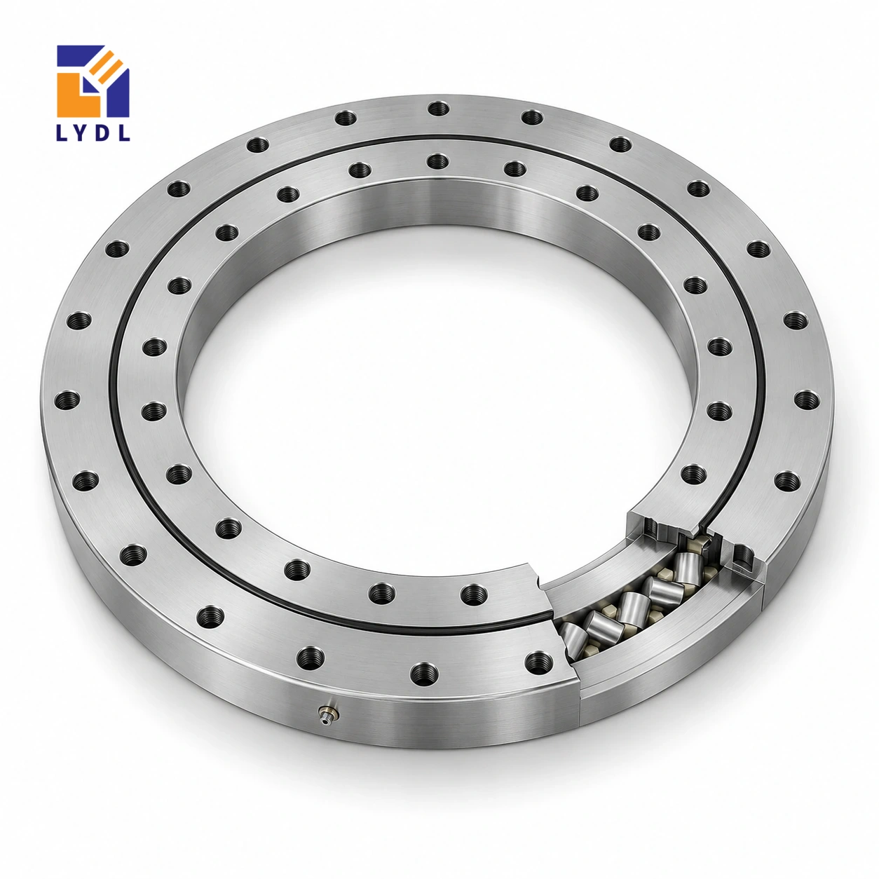
The XU050077 cross roller slewing bearing is a gearless ring reference for a compact rotary joint. Its 40 mm opening, 112 mm outside diameter and 22 mm overall height define the starting envelope; the six-hole connections then determine whether the surrounding plates can accept it.
XU050077 original-reference geometry: Catalogue 404, pp. 90–93. LYDL supply follows its accepted drawing.
XU specification tables · Family technical reference
| Bore (mm) | Outside (mm) | Height H (mm) | Mass ≈ (kg) |
|---|---|---|---|
| 40 | 112 | 22 | 1.4 |
| Outer PCD La (mm) | Inner PCD Li (mm) | Outer holes na | Inner holes ni | Hole dB (mm) |
|---|---|---|---|---|
| 97 | 56 | 6 | 6 | 6.6 |
A miniature indexing fixture can place its motor beside the ring and transmit motion through an independently designed coupling. That arrangement avoids needing teeth on the bearing, but the pulley or drive arm still adds forces to the support. Draw the fixture, workpiece and drive reaction together before selecting the bearing. A small workpiece does not necessarily produce a small overturning moment when its centre of gravity sits well above the rotation plane.
Lay out the 97 mm and 56 mm fixing circles from one coordinate datum. Keep the tool path clear of the neighbouring ring, and verify counterbore details rather than sizing every hole from a rounded web-table value.
For a camera nest, make a drawing of the part surfaces that must remain visible at each indexed angle. Place the optical datum on that drawing instead of assuming it coincides with the rotary axis. A component can be centred mechanically while its inspected feature remains eccentric. Decide whether the acceptance check measures part presentation, fixture runout or image repeatability; these are related but different results.
This turns the small-ring enquiry into a measurable equipment requirement rather than an undefined accuracy request.
The XU050077 dimensions describe several different interfaces. Bore 40 mm and outside diameter 112 mm set the basic radial envelope; overall H = 22 mm sets the bearing's axial reference. Fixing circles La = 97 mm and Li = 56 mm locate the outer and inner attachment patterns, rather than the free opening or roller diameter. The reference lists 6 fixing positions on each ring. A circle and a count do not fully describe a hole: seat details, thread engagement and angular orientation still belong on the accepted drawing. Approximate mass 1.4 kg is a component property, not an approved payload. Reading these fields separately helps prevent a correct catalogue number being transferred to the wrong feature of a mating plate.
Begin an inspection-stage layout with the feature being measured. A cylindrical part may sit concentrically in a nest while a hole, edge or optical target on that part lies away from the rotation axis. Mark that feature and its inspection direction. The resulting requirement might concern presentation to a camera, probe access or angular movement under contact force. Naming the result helps distinguish a bearing dimension from the performance of the completed fixture.
The 40 mm reference bore can provide space for services, but a locating spigot may occupy part of that passage. Show the spigot, fastener engagement and any fixed illumination hardware together. Decide whether the nest is centred by a machined shoulder or by an independently adjustable fixture. Screws that clamp a plate through clearance holes should not silently become its locating system. Include the adjustment range required to align a replacement nest, and identify the surface from which that adjustment will be measured. These details make the small-ring geometry useful to the equipment designer.
Separate the forces applied during inspection from those applied while an operator loads the component. A probe can act near the part centre, whereas a hand pressing on the edge of a fixture applies force farther from the support. A clamp may also pull the workpiece against a stop above the bearing plane. Describe the position and direction of each relevant action, including whether it occurs with the drive holding position.
For the moving phase, list the nest, part and drive attachment as separate rotating items. Their distance from the axis matters to acceleration even if the combined mass is small. State whether the platform indexes between fixed angles, rotates continuously or makes frequent short reversals. Identify the most demanding approved configuration rather than averaging several fixtures. If an external pulley or drive arm is attached to one plate, include its reaction at the actual attachment point. This produces a usable selection brief without assigning a load rating from the compact dimensions.
Establish an observation sequence before changing components. First identify the datum that locates the fixture in the machine, then record how the part is restrained in the nest. Check whether the apparent error changes when the part is reseated, when the nest is removed, or when the direction of rotation reverses. Those observations can separate workholding variation, structural movement and transmission behaviour.
Keep any receiving measurement of the ring distinct from a camera-based test of the completed station. The camera sees the accumulated effects of the bearing arrangement, mounting plates, nest, part and optical setup. Define a repeatable part or target for commissioning and note the loaded condition used. When contacting LYDL, supply the measured concern and its location along with the model reference. A drawing that identifies the required interfaces is more actionable than an unsupported request for the highest precision. The acceptance method can then address the component features that are relevant to the particular inspection task.
A sample order should identify the reference geometry, the offered execution and the intended receiving checks. Ask which drawing revision will accompany the proposal, and retain its relationship to the inspection-nest drawing. Specify the locating and fastening features that must be checked before the mating parts are released for manufacture. Any requirement for running behaviour needs its measurement condition, rather than a descriptive adjective alone.
For storage, keep the bearing and loose nest hardware in separate protected compartments. Small screws and fittings can damage a machined surface during transport even when the overall package remains intact. Preserve identification after unpacking so the sample cannot be confused with another nearby XU size. If a spare is intended for an existing station, record the fixture revision and any adapter used there. That record allows a later order to reproduce the approved arrangement instead of relying on an old photograph. Quantity and destination complete the commercial enquiry, while the drawing and operating brief define the technical proposal.
For an initial dimensional shortlist, place XU050077 (40 × 112 × 22 mm) beside XU060094 (57 × 140 × 26 mm) and XU080120 (69 × 170 × 30 mm). These nearby requested references provide a useful envelope comparison, not a sequence of increasing approved load ratings. Compare their actual bolt circles and support faces before deciding which deserves a detailed drawing review. A smaller bore can conflict with the service route, while a different outside diameter changes the available backing annulus. Retain the complete model in every enquiry so a proposal is tied to the intended row. Only the accepted execution and application assessment can resolve the final choice.
Consider this envelope for a compact inspection nest that rotates a part beneath a camera. The relevant task is supporting the nest and its offset workpiece; camera resolution alone does not establish the bearing accuracy needed.

For this small assembly, request identification, bore and outside-diameter checks, followed by a protected sample package that prevents mounting faces rubbing against loose hardware.

The reference ring occupies a 40 × 112 × 22 mm envelope. Add separate allowances for bolts, locating shoulders and the chosen drive.
No gear teeth are specified for this XU reference. Motion must come from equipment outside the bearing assembly.
The catalogue fixing-hole value is 6.6 mm; the current series web table rounds it. Manufacture the interface from an approved drawing.
Include the workpiece height and eccentricity. These determine moments at the ring even when the payload weighs little.
Identify both mounting faces, centring features, bolt access and the inspection datum. State the acceptance criteria before ordering a sample.
Roller interface comparison: XSU series. Ball-contact option: VU range.
Send the inspection-nest layout, camera offset, moving mass and requested rotation cycle with your XU050077 enquiry.