

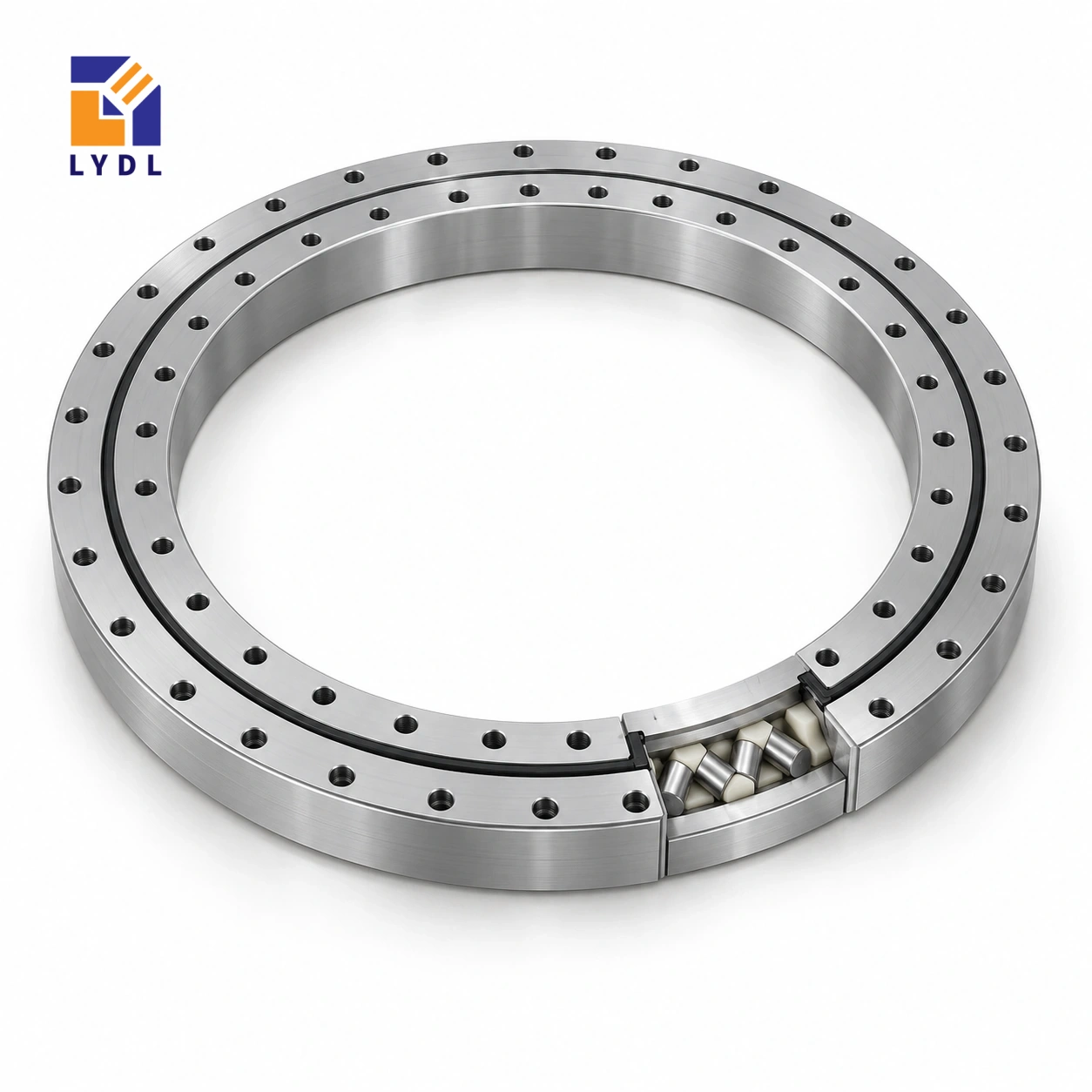
XSU140744 is an ungeared crossed roller bearing reference with a 674 mm bore, 814 mm outside diameter and 56 mm height. Its forty-position ring connections require a coordinated mounting and commissioning plan for the complete rotary platform.
XSU140744: LYDL dimensions; height reference, Catalogue 404 pp. 86–87. Supply is subject to the accepted LYDL drawing.
XSU specification tables · Family technical reference
| Bore (mm) | Outside (mm) | Height H (mm) | Mass ≈ (kg) |
|---|---|---|---|
| 674 | 814 | 56 | 52 |
| Outer PCD La (mm) | Inner PCD Li (mm) | Outer holes na | Inner holes ni |
|---|---|---|---|
| 790 | 698 | 40 | 40 |
The 790 mm and 698 mm fixing circles spread the attachment around the structure, but they do not prevent an uneven support from distorting the ring. Inspect the machined flange after welding and after major subassemblies are attached. Document its supporting condition and decide how rotation resistance will be compared before and after fastening. This helps distinguish a seating problem from an unexpected bearing execution or mechanical interference.
Plan handling, screw access and the staged tightening sequence before the ring reaches the assembly station. Use the approved fastener specification and inspect the final connection without inventing a universal torque from model size.
Record rotation behaviour when the ring is first seated, after fastening and after the tooling frame is attached. Use defined comparable conditions so a change can be traced to an assembly step. Document interference checks around guards and the drive before attempting to compensate with a larger motor. If the base is machined on another fixture, identify the support condition used during measurement.
A drawing that specifies only a nominal flat face does not describe how a flexible fabrication was held for inspection. Keep these records with the equipment commissioning file so later tooling changes can be evaluated against a known baseline.
The XSU140744 dimensions describe several different interfaces. Bore 674 mm and outside diameter 814 mm set the basic radial envelope; overall H = 56 mm sets the bearing's axial reference. Fixing circles La = 790 mm and Li = 698 mm locate the outer and inner attachment patterns, rather than the free opening or roller diameter. The reference lists 40 fixing positions on each ring. A circle and a count do not fully describe a hole: seat details, thread engagement and angular orientation still belong on the accepted drawing. Approximate mass 52 kg is a component property, not an approved payload. Reading these fields separately helps prevent a correct catalogue number being transferred to the wrong feature of a mating plate.
A fabricated table base may be supported differently during machining, inspection and final assembly. Record those conditions where they affect the seating geometry. Show the actual supporting points and the attachment of major brackets. A face that appears satisfactory while clamped in a machining fixture can behave differently when released or connected to the machine frame.
Inspect the completed bearing seat after fabrication operations that can change it. Identify the datum used and the component features to which the offered ring drawing refers. The 814 mm outside envelope and 56 mm height provide layout information, but they do not define the acceptable shape of a finished machine flange. That requirement belongs to the selected execution and structural design. Resolving the seating condition before installation is more useful than expecting the bearing screws to correct a distorted support.
List each tooling set with its mass distribution, workpiece position and process-force locations. Indicate whether combinations of fixtures may remain on the platform at once. The heaviest balanced setup can differ from the most eccentric approved arrangement. Include loading and maintenance states when they impose relevant forces on the support.
State the motion profile with acceleration, reversal and stopping conditions. Show the reaction from the separate drive and any service bundle that moves with the tooling. Define the working datum at which the required behaviour is judged. If a later tooling change extends the reach or raises a process force, revisit that operating case even when the part mass is unchanged. This gives the bearing proposal a controlled equipment context and helps avoid using the catalogue number as an assumed approval for every configuration that can physically fit the table.
Draw the 790 mm and 698 mm fixing circles beside the actual tightening tools and surrounding hardware. Confirm the complete connection geometry from the offered drawing. A clear view of a screw centre does not prove that the tool body fits or that the screw can be withdrawn.
Specify the order of installing the ring, platform, drive, guards and central equipment. Identify which components remain supported during disassembly and how the pinion or separate drive attachment is removed. Include required access cutouts on the structural drawing before the support is assessed. Review local sections under the fixing regions and the path by which forces reach the frame. A documented sequence makes the broad connection practical to assemble and service, without assuming a universal tightening torque or handling method from the bearing diameter alone.
Observe rotation behaviour at defined stages: after seating, after fastening and after adding the tooling and drive. Use comparable conditions and investigate the first stage at which an unexpected change appears. Check for interference and support changes before compensating through a stronger motor or altered control setting.
For equipment acceptance, identify the tooling set, load, measurement point and motion used. For receiving, retain the supplied identity and agreed component checks separately. Keep the bearing drawing and machine revisions with the baseline record. During transport and storage, support the ring without loading seals, fittings or unapproved protrusions, and protect the mounting faces from loose hardware. These practical records make future service enquiries more precise. The page's generic inspection image illustrates a workflow; it does not establish that this exact supplied model has passed a particular test.
The smaller XSU140644 row is 574 × 714 × 56 mm, compared with 674 × 814 × 56 mm here. Its thirty-six positions per ring become forty in this reference. If a large process module drives the choice, show both its operating outline and the path used to remove it through the centre. A nominal opening that accommodates the body may still obstruct its connectors or service tools.
Check the larger annular plate against the actual frame connections and pockets. The constant height cannot establish equal backing or output movement at the tool. Choose a defined layout, obtain the corresponding LYDL execution and evaluate the real forces and motion. Record that complete configuration rather than treating the end of the requested XSU list as an automatic capacity recommendation.
Where the process module is removable, identify its supported state during disconnection and preserve access to the attachment tools throughout the documented maintenance sequence.
A large handling table with interchangeable tooling is one possible use study. Each tooling set changes weight distribution, so describe the worst eccentric configuration as well as the normal arrangement.

Request clear identification and a datum-based measurement record for the accepted execution. Shipping restraints should support the assembly without using lubrication fittings or seal edges as securing points.

The reference envelope is 674 × 814 × 56 mm. Approximate listed mass is 52 kg.
Forty per ring are listed, located on 790 mm and 698 mm fixing circles.
The LYDL order needs its own agreed drawing and acceptance requirement. A reference accuracy entry alone does not establish the supplied result.
Check the final machined seating condition after fabrication steps that can distort it, before the bearing connection is completed.
Identify the most eccentric approved tooling combination, including its payload and process forces. The heaviest balanced setup may not govern.
Other ungeared rollers: XU series. Internal-drive layout: XSI range.
For XSU140744, provide the fabrication sequence, flange inspection plan and heaviest eccentric tooling configuration.