

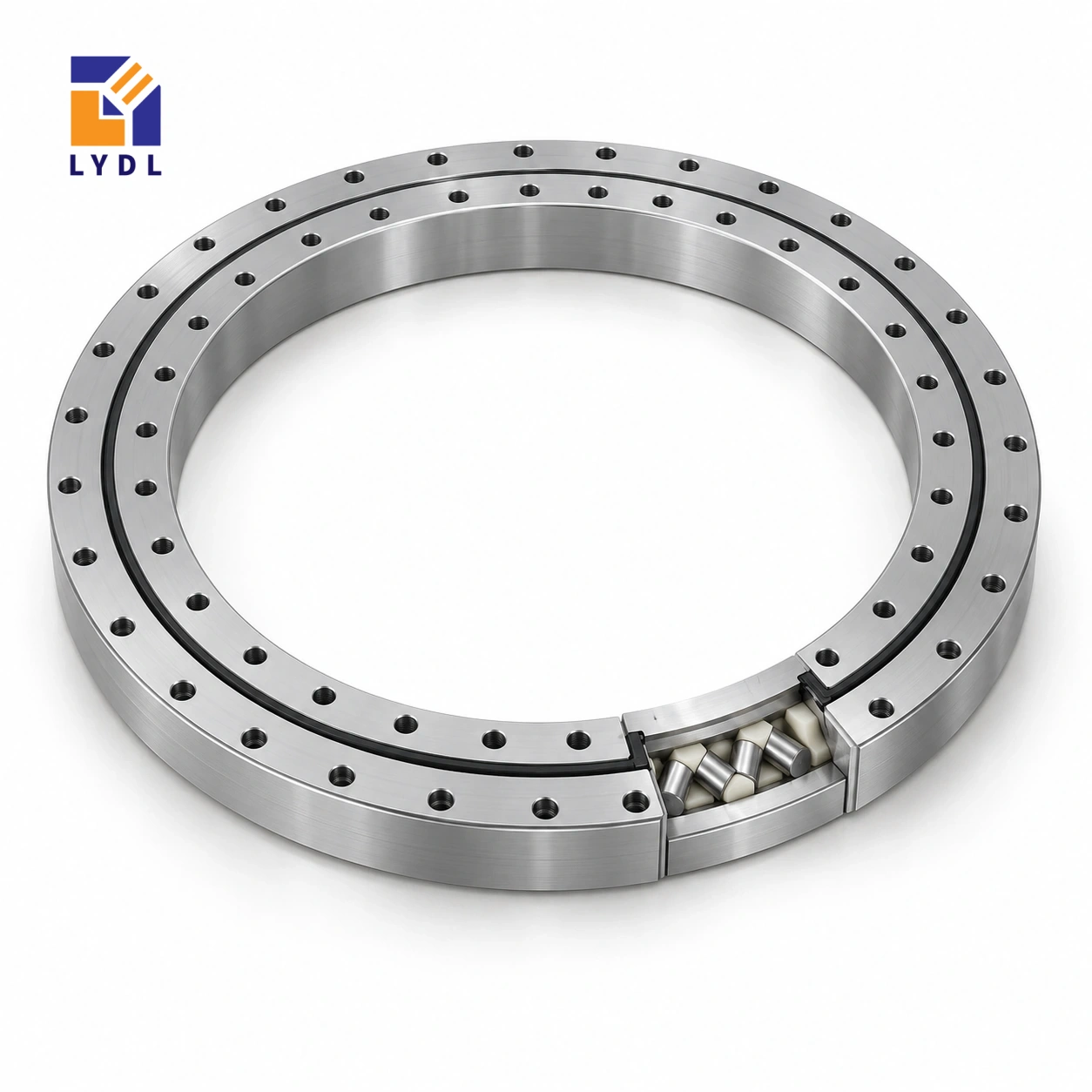
XSU140544 is a gearless crossed roller reference with a 474 mm bore and 614 mm outside diameter. Its 56 mm height and thirty-two-position fixing patterns provide a starting layout for a mid-sized rotary platform with an independently designed drive.
XSU140544: LYDL dimensions; height reference, Catalogue 404 pp. 86–87. Supply is subject to the accepted LYDL drawing.
XSU specification tables · Family technical reference
| Bore (mm) | Outside (mm) | Height H (mm) | Mass ≈ (kg) |
|---|---|---|---|
| 474 | 614 | 56 | 38 |
| Outer PCD La (mm) | Inner PCD Li (mm) | Outer holes na | Inner holes ni |
|---|---|---|---|
| 590 | 498 | 32 | 32 |
A belt or friction drive may appear to avoid gear-interface work, but its tension and bracket reactions still enter the bearing support. Show where those forces act relative to the ring plane. Keep the drive bracket and the 590 mm/498 mm fixing circles on one assembly drawing so clearances can be checked together. The drive concept also determines whether service work requires removing the rotating platform or only a peripheral component.
Review mounting-face support near the drive bracket and avoid attaching concentrated loads to an unsupported flange sector. Define service access for the completed machine, including any lubrication connections confirmed on the ordered execution.
Show belt forces as a pair acting through the actual pulley and bracket rather than as a single motor-torque figure. Indicate the belt plane relative to the ring seating and identify how the fixed structure receives the bracket reaction. Tension adjustment can also move the motor or pulley into a maintenance envelope that the nominal operating layout misses. If a friction wheel is proposed instead, provide the normal contact force and its location.
These arrangements are transmission choices with different support reactions, despite both being compatible in principle with an ungeared ring. Confirm the selected concept before asking for final connection details or acceptance checks.
The XSU140544 dimensions describe several different interfaces. Bore 474 mm and outside diameter 614 mm set the basic radial envelope; overall H = 56 mm sets the bearing's axial reference. Fixing circles La = 590 mm and Li = 498 mm locate the outer and inner attachment patterns, rather than the free opening or roller diameter. The reference lists 32 fixing positions on each ring. A circle and a count do not fully describe a hole: seat details, thread engagement and angular orientation still belong on the accepted drawing. Approximate mass 38 kg is a component property, not an approved payload. Reading these fields separately helps prevent a correct catalogue number being transferred to the wrong feature of a mating plate.
Draw both belt spans, the driven attachment and the motor support rather than representing the transmission only by an output torque. Belt tension can impose forces whose direction and application height matter to the ring and base. Show the belt plane relative to the bearing seating and identify how the bracket returns its reaction into the fixed structure.
Include the adjustment travel used to tension the belt and the space needed to remove it. A drive can fit in operation while becoming inaccessible beneath a platform or guard. If a friction wheel is proposed instead, describe its contact force and support arrangement as a different transmission case. The ungeared reference gives the designer this choice, but the alternatives do not create identical support reactions. Confirm the intended concept before finalising the flange or requesting an application-specific component proposal.
The 474 mm opening can accommodate a substantial central feature, but it does not define the payload position. Place the transferred part, gripper and tooling on the platform drawing at their actual radii. Show pickup and release configurations separately if the centre of gravity moves. Include any force from engaging a guide or neighbouring station.
State acceleration, stopping and normal reversals, together with the mass distribution that moves during each phase. Stationary process reactions should be listed independently. A platform that appears balanced when full can be eccentric when partially loaded. Define the approved occupancy combinations rather than averaging them. This information gives the bearing and transmission review a clear operating basis. It also identifies what must be reconsidered if a later tool extension or drive-tension change alters the machine without changing the nominal product weight.
Place the 590 mm and 498 mm fixing circles over the actual base and upper-plate sections. Show local pockets, access holes and the attachment of the drive bracket. The force path from that bracket may enter a flange sector differently from the distributed platform load. Review both within the manufactured structure.
Confirm the complete screw and centring details for the offered execution. Check access to all thirty-two positions per ring with the bracket and service equipment installed. Identify which guards are removed for tightening or inspection and how those parts are supported during service. Inspect the completed seating in its assembly condition rather than assuming the initial fabrication dimensions remain unchanged. A clear connection drawing links the nominal reference to practical manufacture and helps prevent late access modifications from changing the support that was originally assessed.
Agree the received component's identification, drawing features and any functional observation under stated support conditions. Separately define the finished platform result, including its measurement point, payload and motion. A successful free-running sample does not by itself demonstrate the loaded behaviour of the assembled table.
Record the drive adjustment and tooling configuration used at commissioning. Keep the bearing drawing, bracket revision and load schedule together so later comparisons use equivalent conditions. Describe cleaning, contamination and idle storage when discussing the supplied sealing, lubrication and packing arrangements. Protect machined faces and avoid using an unapproved ring feature as a handling point. For a repeat order, provide the actual accepted configuration and requested quantity. This gives LYDL a technical record to follow without relying on a family photograph or an unsupported assumption about precision or allowable load.
For the belt-driven platform, XSU140414 offers a smaller 344 mm opening and 484 mm outside boundary; XSU140644 offers 574 mm and 714 mm. This model's 474 mm opening sits between them. Their respective attachment counts are twenty-four, thirty-two and thirty-six per ring at the same listed 56 mm H.
Keep the belt plane and its bracket on each comparison section. A changed ring diameter may require a different driven attachment and tensioning route even where the platform level stays unchanged. Check how those forces enter the support rather than assuming that common height preserves the drive. The accepted candidate needs its own supplied connection details and assessment of the actual occupancy, motion and belt reaction.
Record belt adjustment alongside the platform test condition. A later tension change can alter transmission reactions, so compare the actual setting and bracket state before attributing a changed observation solely to the ring.
A material-handling platform with an edge-mounted drive is an illustrative case. Describe load eccentricity at pickup and the drive forces during acceleration before assigning a suitable bearing configuration.

Discuss dimensional checks and the rotation-test condition before ordering. Specify how the shipping support will prevent the drive-side edge being used as an improvised lifting point.

The nominal reference is 474 × 614 × 56 mm, with approximate mass 38 kg in the listed data.
Thirty-two positions per ring are listed on 590 mm outer and 498 mm inner fixing circles.
Belt tension can introduce radial forces. Include the belt geometry and tension in the equipment load analysis.
Its connection needs structural review. Avoid assuming an adjacent thin flange can accept a concentrated bracket reaction.
Show the platform, guards, drive and confirmed service fittings in their installed positions, including the tools needed for removal.
Other ungeared rollers: XU series. Internal-drive layout: XSI range.
Provide the belt tension or drive-contact forces, bracket drawing and platform inertia with XSU140544.