

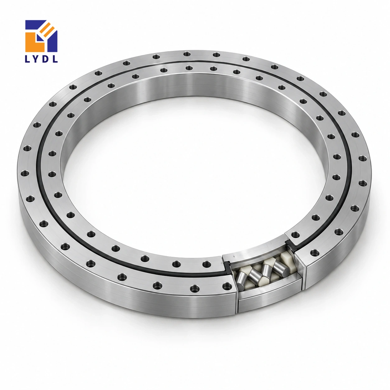
The XSU080318 cross roller slewing bearing reference combines a 280 mm bore, 355 mm outside diameter and 25.4 mm height. It is ungeared, allowing the machine designer to choose a separate drive while keeping a broad centre passage.
XSU080318: LYDL dimensions; height reference, KSX pp. 54–55. Supply is subject to the accepted LYDL drawing.
XSU specification tables · Family technical reference
| Bore (mm) | Outside (mm) | Height H (mm) | Mass ≈ (kg) |
|---|---|---|---|
| 280 | 355 | 25.4 | 6.3 |
| Outer PCD La (mm) | Inner PCD Li (mm) | Outer holes na | Inner holes ni |
|---|---|---|---|
| 340 | 295 | 28 | 28 |
A mechanism that rocks through a short angle may accumulate many reversals while seldom making a full revolution. Specify the angular travel, dwell time and cycle frequency, then discuss the lubrication arrangement for that motion. The 340 mm and 295 mm fixing circles help define the support interface, but they do not establish how a short-stroke duty will behave. Include contaminant exposure and idle periods in the operating description.
Twenty-eight fixing positions are listed on each ring. Preserve room for tools and check the final enclosure design before assigning service points, guards or sensors around the periphery.
Record the smallest normal angular stroke, not only the largest occasional movement. Include pauses and any repeated reversal at the same location. State whether the mechanism sometimes makes a full revolution during servicing and whether that movement is part of the approved maintenance procedure. The lubricant proposal needs the actual motion and environment.
Avoid adding an arbitrary servicing rotation or interval to the page; it should be determined for the ordered configuration and the equipment operating schedule.
The XSU080318 dimensions describe several different interfaces. Bore 280 mm and outside diameter 355 mm set the basic radial envelope; overall H = 25.4 mm sets the bearing's axial reference. Fixing circles La = 340 mm and Li = 295 mm locate the outer and inner attachment patterns, rather than the free opening or roller diameter. The reference lists 28 fixing positions on each ring. A circle and a count do not fully describe a hole: seat details, thread engagement and angular orientation still belong on the accepted drawing. Approximate mass 6.3 kg is a component property, not an approved payload. Reading these fields separately helps prevent a correct catalogue number being transferred to the wrong feature of a mating plate.
An oscillating arm should be described by the movement it actually makes. Give its minimum routine stroke, maximum travel, reversal frequency and time spent at each end. Identify occasional full rotations separately, including whether they are permitted during servicing. An average speed does not communicate how motion is distributed over the cycle.
Show the payload at pickup and delivery with its support conditions. State whether the arm retracts before movement or changes radius while it turns. Include forces from engaging another machine component. The mass distribution of the arm, gripper and product can change while the bearing itself remains in one location.
Provide these observations when discussing the supplied lubrication and running execution. Do not invent a servicing rotation or interval from the model name. The proposal should address the stated motion and environment. Retain the approved operating sequence with the machine documentation so a later control change can be checked against the selection basis rather than assumed to be equivalent.
The 280 mm bore reference can be useful for equipment passing through the centre, but its real usable space depends on pilots, fasteners and installed services. Draw the complete passing component with connectors and its temporary assembly envelope. Identify whether it can be removed while the arm and ring remain mounted.
Place the 340 mm and 295 mm fixing circles on the same layout with the actual tools. Twenty-eight positions on each ring require a workable tightening and removal sequence around the machine. Check how covers, sensors or the drive support affect that sequence. A small access slot can influence local flange support, so include it on the structural drawing used for review.
The ungeared arrangement also needs a defined transmission. Show the part that applies motion and where its reaction reaches the fixed structure. Keeping these interfaces visible prevents the centre opening, fastening pattern and drive layout from being treated as independent space checks that conflict when the assembly is built.
Choose the useful equipment datum, such as a gripper location under a stated force, before assigning an accuracy requirement. Motion there can include arm bending, bracket deformation, transmission response and the bearing arrangement. A component receiving check does not by itself measure that complete result.
Agree the supplied model, drawing and required receiving features. Record the support condition for any functional observation. At commissioning, document the arm configuration, payload and motion used for comparison. A changed cable restraint or gripper extension should be considered when later readings differ. This helps avoid attributing a system change to the ring without supporting evidence.
State the expected idle periods, contamination and cleaning exposure when defining storage protection and the offered execution. Pack the ring on a stable support with loose service fittings separated from machined faces. Keep the accepted proposal and operating sequence together for spare ordering. The published dimensions support an initial selection discussion, while the actual supplied drawing and application assessment establish the final component requirements.
XSU080258 provides a 220 mm opening and 295 mm outside envelope, while XSU080398 provides 360 mm and 435 mm respectively. The present 280 mm bore and 355 mm outside diameter form a distinct intermediate option. Twenty-eight attachment positions per ring also differ from the twenty-four and thirty-six of those neighbours. A platform designed around one of these rows needs its own mating patterns.
For a rotating arm, compare the bracket footprint and working radius on each proposal. The arm load does not move closer to the bearing merely because the nominal ring becomes larger. Preserve its actual application point in the layout. Show the central services with their restraint and maintenance access so the larger opening is assessed for a real purpose.
The reference height stays at 25.4 mm for these XSU08 sizes. Plates, adapters and the drive can nevertheless produce different completed stack heights. Mark the fixed equipment datums before making a selection. Resolve the supplied pilot and fastening execution through LYDL's drawing, then review the arm duty and desired observation at the gripper. Geometry supports that discussion without supplying an undocumented system accuracy or load rating.
For an arm with several grippers, show which grippers can carry parts simultaneously. Their occupancy changes the moving mass distribution and can shift the relevant force case. Preserve the approved combinations in the equipment record rather than assuming that every arrangement is equivalent.
An oscillating material-handling arm is a suitable example for engineering review. Model its pickup and delivery angles separately because load orientation and cable reaction can change between them.

Request functional checks under stated test conditions and identify the intended operating motion. Keep the assembly supported during transport without applying force to exposed service fittings.

Its nominal reference envelope is 280 × 355 × 25.4 mm, before allowances for mounting plates, bolts and the external drive.
There are twenty-eight per ring, with 340 mm outer and 295 mm inner fixing circles.
No. Describe the actual angular stroke and reversals so lubrication and operating behaviour can be reviewed for that duty.
Check the actual pilots, inner connection and passing equipment. Nominal bore size does not account for every obstruction in the assembled machine.
Long stops can change preservation and restart needs. State the storage and operating environment instead of supplying only an average cycle rate.
Other ungeared rollers: XU series. Internal-drive layout: XSI range.
Send XSU080318 enquiries with oscillation angle, reversals per hour, idle periods and the arm-load sketch.