

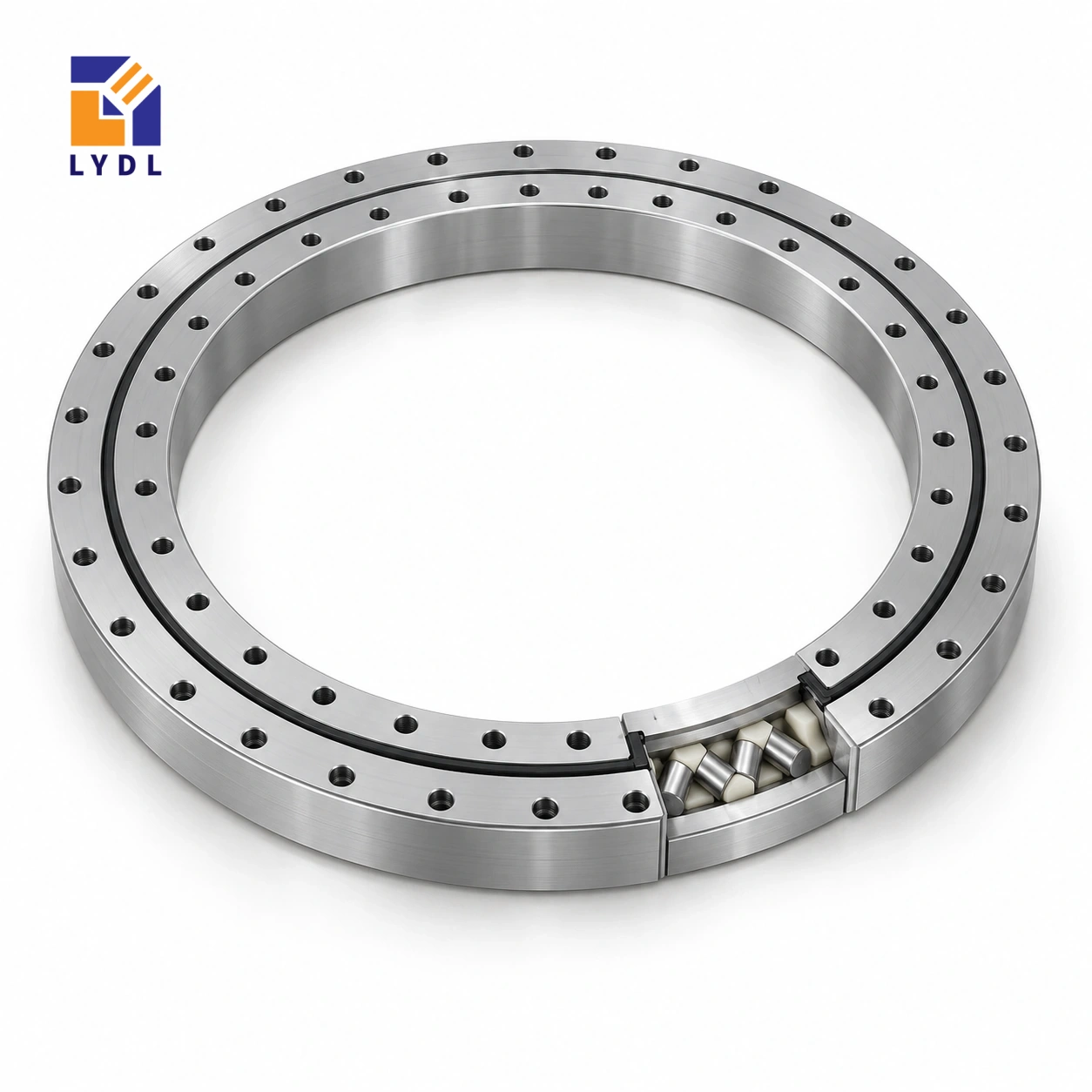
XSU080258 is an ungeared cross roller reference with a 220 mm bore and 295 mm outside diameter. Its shallow 25.4 mm section can be assessed for a rotary table where the centre opening and the supporting flange are both constrained.
XSU080258: LYDL dimensions; height reference, KSX pp. 54–55. Supply is subject to the accepted LYDL drawing.
XSU specification tables · Family technical reference
| Bore (mm) | Outside (mm) | Height H (mm) | Mass ≈ (kg) |
|---|---|---|---|
| 220 | 295 | 25.4 | 5.1 |
| Outer PCD La (mm) | Inner PCD Li (mm) | Outer holes na | Inner holes ni |
|---|---|---|---|
| 280 | 235 | 24 | 24 |
The bearing connects through twenty-four positions on each ring, with fixing circles of 280 mm and 235 mm. Those connections must transmit the forces from any overhung nest or gripper into the base. Record how far the force acts from the bearing plane and whether its direction reverses during operation. A low bearing height does not automatically mean the upper assembly can be thin; the backing structure has its own bending requirement.
Check contact coverage beneath the fixing regions rather than leaving isolated pads under individual bolts. Confirm the fastener and seating details before deciding how the upper fixture will be removed for maintenance.
A supporting plate can appear thick in its central section but offer little contact beneath the fixing annulus. Examine the local section where the ring actually sits, including pockets, ribs and machining reliefs. Provide a drawing showing the bearing footprint over those features. The load must reach the machine frame through that structure.
Tightening an unsupported region against the ring is not a substitute for a defined seating surface, and a free-ring inspection cannot validate the assembled backing plate.
The XSU080258 dimensions describe several different interfaces. Bore 220 mm and outside diameter 295 mm set the basic radial envelope; overall H = 25.4 mm sets the bearing's axial reference. Fixing circles La = 280 mm and Li = 235 mm locate the outer and inner attachment patterns, rather than the free opening or roller diameter. The reference lists 24 fixing positions on each ring. A circle and a count do not fully describe a hole: seat details, thread engagement and angular orientation still belong on the accepted drawing. Approximate mass 5.1 kg is a component property, not an approved payload. Reading these fields separately helps prevent a correct catalogue number being transferred to the wrong feature of a mating plate.
Draw the actual seating region under the bearing rather than assuming the whole plate backs it. The 295 mm outside envelope can fit a fixture base whose contact surface is interrupted by pockets or local pads. Show those features beside the 280 mm outer fixing circle and identify how forces reach the frame.
A workpiece extending beyond the nest can load the connection differently as it rotates. Mark the centre of gravity and each clamp or process force relative to the bearing plane. Include the upper plate and its attachment, because deflection there can affect the observed workpiece position. The 25.4 mm reference height describes the ring package and does not specify a suitable plate thickness.
Decide how the nest is centred and whether its angular orientation is fixed or adjustable. Keep those locating features distinct from clearance holes used for clamping. If an adapter is required, draw both of its interfaces and include its effect on the working height. These details turn the nominal dimensions into a reproducible machine connection.
Show the approved workpiece range and the clamp arrangement for each relevant setup. An irregular part can change its gravity moment as it turns even when its mass remains constant. Include the position used for loading and the orientation used during the process. State whether clamps or tooling apply force while rotation is stopped.
The electrical return and its flexible connection also belong on the equipment layout. Route them according to the machine design rather than relying on the bearing as a return path. If a cable or hose exerts a significant changing reaction, identify its restraint and travel. Review shielding against process debris without blocking access to the twenty-four-position connections.
For motion, provide the moving assembly distribution, angular travel and programmed stops. Distinguish normal reversal from a separate emergency event where applicable. A representative welding image illustrates a possible task; it does not establish suitability for a specific current, heat exposure or contamination condition. Those requirements need to be described for the offered configuration and the surrounding enclosure.
Identify which component dimensions must be accepted before the mating plates are completed. Use the agreed drawing revision and measurement datum. Keep any running observation tied to its support condition so it can be interpreted correctly. A free component and a bolted fixture are different test arrangements.
During assembly, inspect the prepared seating and confirm that tools reach all required fasteners. Compare behaviour after the ring, nest and separate drive are added. If resistance changes unexpectedly, examine the stage where it appeared before changing drive settings. For equipment acceptance, use a named workpiece configuration and the load condition relevant to the specified result.
Retain the sample approval record, bearing proposal and fixture drawing together. Protect machined faces from loose clamp parts during shipment and storage. Quantity, destination, workpiece diagrams and required inspection evidence complete a practical enquiry. These records support repeat ordering and future maintenance without turning approximate catalogue geometry into an undocumented precision, preload or service-life guarantee.
The step from XSU080218 to this model increases the nominal bore from 180 to 220 mm and the outside diameter from 255 to 295 mm. The fixing count changes from twenty to twenty-four on each ring. XSU080318 continues to 280 mm bore, 355 mm outside diameter and twenty-eight positions per ring. All three use a 25.4 mm height reference, but that common entry does not preserve the surrounding flange sections.
Draw the intended central equipment and arm attachment at each candidate size. If a stationary service bundle is the main constraint, check its connector and removal route rather than choosing an opening only from the bundle's operating diameter. If an arm governs the design, show its force path into the annular plate and the material available around each pattern.
The comparison should identify a specific reason to retain one candidate: a fixed machine opening, available backing or a practical assembly route. It should not become a ranking of stiffness or payload derived from the model sequence. Ask for the offered execution of the selected reference and attach the duty cases. Retain the arm and service-layout revisions with that enquiry so later changes do not silently invalidate the original assumptions.
If a rotating arm is exchanged, identify its locating datum and document the new bracket revision with the permitted operating configuration before comparing results.
A welding fixture that rotates an irregular component is a representative case. Describe the changing centre of gravity and the forces from clamps, without treating the pictured application as a verified installation.

Discuss an inspection setup that records the ring support condition. Specify surface protection and separators so the packed faces do not rub during handling.

The XSU08 reference height is 25.4 mm for this 220 mm-bore, 295 mm-outside-diameter size.
Twenty-four positions per ring are listed on 280 mm and 235 mm circles. Obtain the hole-detail drawing before manufacture.
The supporting plate still needs adequate stiffness. Evaluate its deformation under the actual forces instead of choosing thickness from bearing height.
Clamp forces and a moving centre of gravity can add moments beyond the component weight. Include both in the selection data.
Identify the supporting surfaces, fastening condition and measurement datum. These conditions affect how a rotation measurement should be interpreted.
Other ungeared rollers: XU series. Internal-drive layout: XSI range.
Include maximum component overhang and the complete clamp arrangement when enquiring about XSU080258.