

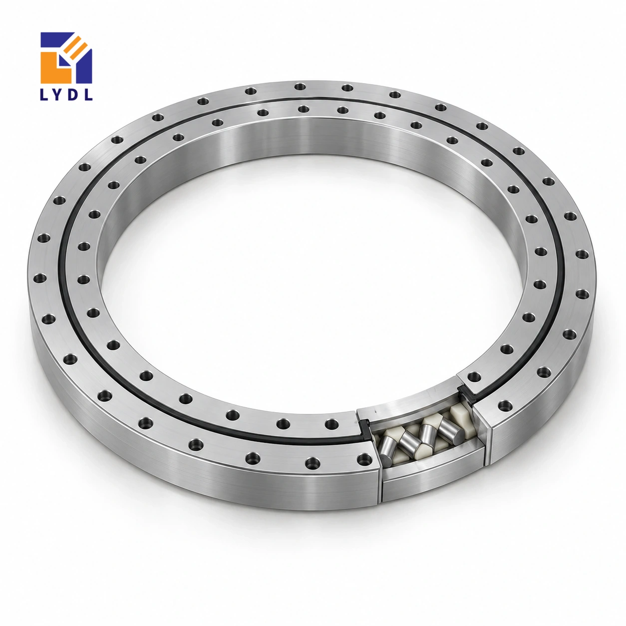
An XSU080218 cross roller slewing bearing offers a 180 mm bore within a 255 mm outside envelope. This ungeared XSU08 reference has a 25.4 mm height and twenty fixing positions per ring; the detailed centring interface must be settled before machining.
XSU080218: LYDL dimensions; height reference, KSX pp. 54–55. Supply is subject to the accepted LYDL drawing.
XSU specification tables · Family technical reference
| Bore (mm) | Outside (mm) | Height H (mm) | Mass ≈ (kg) |
|---|---|---|---|
| 180 | 255 | 25.4 | 4.3 |
| Outer PCD La (mm) | Inner PCD Li (mm) | Outer holes na | Inner holes ni |
|---|---|---|---|
| 240 | 195 | 20 | 20 |
The basic diameters and 240 mm/195 mm fixing circles provide a reliable starting comparison. They do not fully define the pilot steps. When a series table and an original reference drawing differ on an auxiliary diameter, use the approved LYDL drawing for that feature instead of mixing values from different sources. Keep the bore, support shoulder and fixing-circle definitions separate on the customer drawing so the production check can identify each feature unambiguously.
Review shoulder heights and any relief at the mounting corner. Bring the mating parts together without forcing the ring over an uncertain pilot; investigate an unexpected fit before tightening screws.
Give each locating feature a unique drawing label and state which component mates with it. That prevents a discussion of one auxiliary diameter from being confused with the main bore. For the first manufactured assembly, plan a dimensional fit review before all fixtures are completed. Record the accepted revision in the enquiry and inspection requirements.
The omitted auxiliary pilot value on this page is intentional: using a confirmed drawing is more useful than presenting an unresolved number as final engineering data.
The XSU080218 dimensions describe several different interfaces. Bore 180 mm and outside diameter 255 mm set the basic radial envelope; overall H = 25.4 mm sets the bearing's axial reference. Fixing circles La = 240 mm and Li = 195 mm locate the outer and inner attachment patterns, rather than the free opening or roller diameter. The reference lists 20 fixing positions on each ring. A circle and a count do not fully describe a hole: seat details, thread engagement and angular orientation still belong on the accepted drawing. Approximate mass 4.3 kg is a component property, not an approved payload. Reading these fields separately helps prevent a correct catalogue number being transferred to the wrong feature of a mating plate.
Give the bore, locating shoulders and fixing circles separate feature labels on the mating drawing. The 180 mm opening and the 240 mm and 195 mm attachment circles provide useful nominal information, but they do not define every pilot step. An auxiliary diameter with inconsistent source entries should be resolved on the offered LYDL drawing before it becomes a manufacturing dimension.
Identify the component that mates with each locating feature and state how the fit will be assessed. If the machine drawing comes from a measured existing part, record the measuring location and whether that part was assembled or free. An accessible cover or relief can be mistaken for a bearing diameter if the component boundaries are unclear.
Plan a dimensional review of the first mating assembly before completing the remaining fixtures. Keep the accepted revision linked to the ring, upper plate and base. Do not use the fixing screws to pull an uncertain pilot into place. This approach preserves the useful published envelope while making the unresolved detail explicit and giving the enquiry a concrete route to completion.
Show the illumination unit, workpiece holder and services through the centre of the platform. Include the temporary space required to install a connector or remove a light housing. An operating clearance can be adequate while the maintenance route is blocked by the inner connection or drive. Decide which components can be removed independently of the ring.
Define what the inspection station measures and where the relevant datum lies. The part may rotate about one mechanical axis while its inspected surface is intentionally offset. State how the nest locates the part and how it is reseated between cycles. The complete imaging result includes workholding, support, optical alignment and motion, so it should not be assigned to bearing dimensions alone.
Describe the angular movement and any contact or clamping forces applied during inspection. Include the fixture and service reactions in the load sketch. If the machine alternates between several nests, identify their separate geometry and permitted loading configurations. These details help establish a useful requirement for the supplied execution and for the completed station, without inventing a precision grade or an optical-performance claim for the model.
The receiving plan should identify the supplied model, accepted drawing and the features that must match the mating parts. Where a pilot has been resolved during proposal review, retain that final decision in the drawing rather than in a separate informal note. Specify the measurement datum and support condition relevant to any agreed dimensional or functional check.
At assembly, inspect the mounting surfaces and remove interference before fastening. Compare the station at defined stages so a change in rotation behaviour can be associated with the plate, drive or services that were added. For equipment acceptance, use a repeatable target and a documented nest configuration. Keep that record distinct from component receiving inspection.
Discuss contamination from the inspected parts, the cleaning method and expected idle storage when defining protection and the offered sealing arrangement. Pack the ring away from loose illumination brackets and fittings. A future spare order should identify the accepted pilot and machine revision, not simply the public row from which the study began. This keeps the page useful as a reference while the actual supply remains tied to confirmed geometry.
XSU080188 is smaller at 150 × 225 × 25.4 mm, whereas XSU080258 is larger at 220 × 295 × 25.4 mm. The present 180 × 255 × 25.4 mm envelope lies between them in opening and outer footprint. Their fixing counts progress from sixteen to twenty to twenty-four per ring. Use those actual entries when drawing possible bases; the three rings do not share one attachment pattern.
For an illuminated inspection fixture, determine whether the optical housing or its replacement route sets the opening. A twenty-millimetre increase in radial clearance can be useful only if it addresses the real obstruction. Check the outside boundary against the camera supports and machine enclosure as well. The height common to these references does not define the entire optical stack.
An unresolved auxiliary pilot entry for XSU080218 remains a drawing question even when its neighbouring envelopes are well understood. Do not interpolate that feature from another row. Submit the intended light unit and mating flanges for a defined offer. Keep the resolved pilot, optical alignment method and nest configuration together when assessing the first assembly and ordering a spare.
A compact rotary inspection platform could use this open centre for a fixed illumination unit. Check clearances between the rotating table, light housing and service connections across the entire cycle.

Agree how pilot diameters and locating faces will be measured. Reference the accepted drawing revision on the packing identification so the incoming inspection uses the same geometry.

The main envelope is 180 × 255 × 25.4 mm. Fixing circles are 240 mm and 195 mm, with twenty positions per ring.
No. Auxiliary pilot details require the accepted LYDL drawing; an unresolved pilot value is deliberately not presented as a machining dimension.
Resolve the fit first. Fasteners should not be used to pull an uncertain interference fit into place.
Its housing and cables can occupy the rotating envelope. Check them at every angular position, including maintenance access.
Use one agreed drawing revision, clearly named datums and identified pilot features. A model number without revision control is insufficient for that check.
Other ungeared rollers: XU series. Internal-drive layout: XSI range.
Send the proposed pilot section and light-housing clearance study with the XSU080218 model request.