

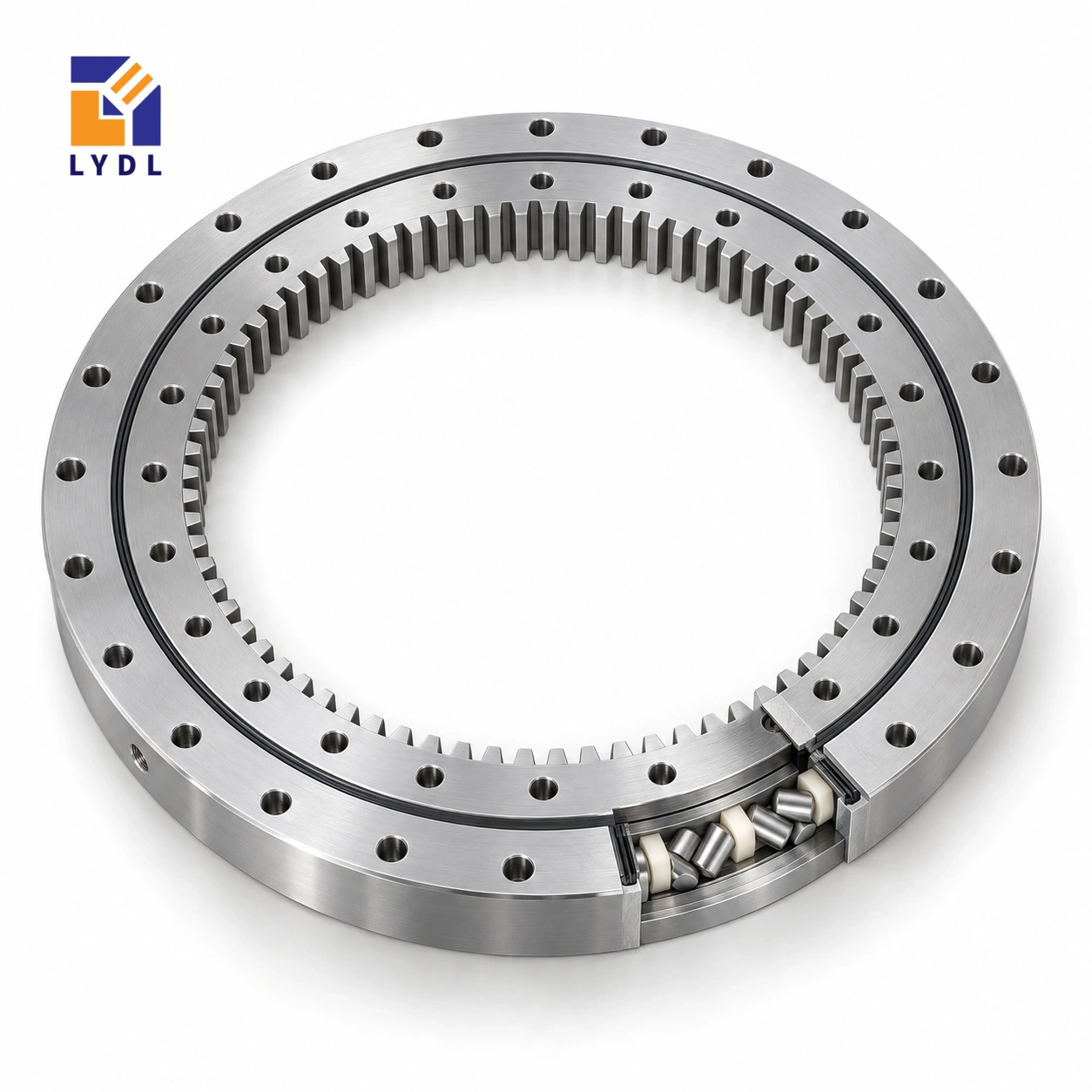
XI180635 is a LYDL-listed internally geared crossed roller reference measuring 504 × 722 × 54 mm. It uses a module 8, 65-tooth gear listing and twenty-four fixing positions per ring, requiring both a drive study and a flange-load review.
XI180635: nominal LYDL listing. INA interchange unverified. Supplied execution requires an agreed drawing.
XI specification tables · Family technical reference
| Bore (mm) | Outside (mm) | Height H (mm) | Mass ≈ (kg) |
|---|---|---|---|
| 504 | 722 | 54 | 67 |
| Outer PCD La (mm) | Inner PCD Li (mm) | Outer holes na | Inner holes ni | Hole dB (mm) | Secondary h (mm) |
|---|---|---|---|---|---|
| 690 | 580 | 24 | 24 | 18 | 47 |
| Pitch d0 (mm) | Module m (mm) | Teeth z | Width b (mm) |
|---|---|---|---|
| 520 | 8 | 65 | 47 |
The internal gear can transmit rotation while the bearing supports equipment forces through a separate load path. A specified motor torque therefore cannot stand in for axial, radial and overturning-load data. Mark each force and its point of application on a section through the platform. The 520 mm pitch diameter helps describe the transmission, but permissible tooth force and bearing performance must come from the accepted execution and its applicable engineering assessment.
Use the 690 mm outer circle and 580 mm inner circle to review connection access. Check the 18 mm fixing-hole entry and the stated 47 mm gear width against the offered model drawing.
List gravity, clamp reactions and process forces as separate entries, each with a direction and application point. An external process force may pass through the bearing axis in one workpiece orientation and create a substantial lever arm in another. Show the approved rotation range and identify the positions that bound the design review. The drive torque can be associated with those states, but it should not replace their force descriptions.
If a gearbox is selected before the bearing, provide its output data and the proposed pinion rather than only the motor nameplate. Include the bracket support and any adjustment mechanism. Clarify how mesh alignment will be checked after the positioner frame is welded and machined. The accepted component drawing defines the purchased ring; the machine drawing defines the mounting condition in which it operates.
Keep both revisions in the commissioning record. For a welding application, show the return-current route and protective covers in that same equipment package. The bearing page does not certify the electrical design or establish a permissible welding exposure. Those boundaries should be resolved through the complete equipment design.
The XI180635 gear row describes internal teeth with module 8 and 65 teeth. Their product is 520 mm, matching the listed nominal pitch diameter. That arithmetic checks the relationship between three entries; it does not calculate a permissible tooth force. The physical outside diameter is 722 mm and the bore is 504 mm, so neither should be replaced by the pitch-circle value in a clearance drawing. Overall height H is 54 mm. Locate the gear face and the two mounting planes from the offered section before positioning a pinion. The tooth form, engagement, quality requirement and supplied material execution remain separate specification items. Keeping these definitions distinct prevents a correct transmission number from being used as the wrong housing dimension.
Show the weldment, positioner arms and clamps at their operating locations. The 504 mm central opening is a useful layout reference, but the internal pinion and its support occupy some of the same region. Include the workpiece loading path and the space needed to operate clamps. A convenient welding orientation can be awkward to assemble if these activities are considered only after the drive is fixed.
Identify the workpiece centre of gravity in each permitted orientation. Describe process contact, cable drag and any unbalanced tooling. Include idle dwell under load as well as rotation. These details establish the equipment cases that require review; the 67 kg approximate component mass says nothing about the permissible mass of a welded assembly.
Indicate where welding heat enters the fixture and how the structure is connected to the bearing seating. Record the process duration and cooling interval rather than assuming that workshop ambient temperature describes the ring. The proposed supply execution needs assessment against that thermal context.
Draw the welding-current return path and its flexible connections. Do not depend on rolling contacts as an undocumented return route. Locate covers that deflect spatter and debris while preserving the agreed maintenance access. If cleaning fluid is used, describe its direction and frequency. The shared application picture provides an example of a positioning task; it is not evidence of electrical isolation, heat resistance or successful operation of XI180635 in that process.
The gear reference is module 8 with 65 teeth and a 520 mm pitch circle. Show the pinion shaft and bracket relative to the inner ring section. Check how fabrication, machining and final bolting establish those datums. A bracket placed by an overall frame dimension may not hold the intended relationship at the mesh after assembly.
The fixing circles, 690 mm outside and 580 mm inside, must be backed by the actual frame sections. Account for cutouts, gussets and local changes near the motor support. Confirm the screw details at all twenty-four positions per ring and check tool access behind guards. Discuss the method of setting and checking the transmission with the supplier, without inventing a universal backlash or tightening value.
Write the component inspection request separately from the machine's welding-position test. For the latter, identify workpiece configuration, approach direction, dwell time and the datum being observed. Keep the relevant frame and drive settings in the commissioning record so later comparisons are meaningful.
For procurement, supply the fixture drawing, operating schedule and required quantity. The LYDL nominal listing supports this enquiry but does not prove a direct INA interchange for the extended reference. Resolve the offered section and service features before releasing mating parts. Request packing that protects the agreed machined interfaces and keeps loose fixture hardware from contacting them during transport. Any requested test evidence should be tied to the ordered execution.
XI200720 is another module 8 reference, but it has 75 rather than 65 teeth and a 584 × 812 × 58 mm envelope. This row is 504 × 722 × 54 mm. A common module can simplify the comparison of tooth geometry, yet the ring-to-pinion count relationship and physical installation still change.
For a welding fixture, preserve the workpiece and clamp positions on both candidate sections. Check which opening is needed for the loading route and current-return assembly, and how the changed flange size reaches the frame. Resolve the offered drawing and actual welding duty before purchasing. Neither the larger envelope nor the shared module supplies an approved thermal, electrical or load specification.
Keep the weldment revision with each recorded positioning observation.
A welding-positioner support is an example where gravity, clamp forces and drive torque act together. State the worst workpiece orientation and keep the electrical return design separate from the rolling contact.

Discuss geometric checks at the gear and the mounting datums before agreeing acceptance. Shipping restraints should hold the ring without loading tooth tips or service fittings.

LYDL lists a 504 mm bore, 722 mm outside diameter and 54 mm height, with approximate mass 67 kg.
Module 8, 65 teeth and 520 mm pitch diameter are listed. The gear-width entry is 47 mm.
No. Supply axial and radial forces and overturning moments separately, including their positions and duty.
No. It identifies the website reference. This extended model requires LYDL drawing confirmation and does not carry an independently verified INA interchange claim here.
Its centre of gravity changes relative to the support plane. Evaluate the complete orientation range rather than only the loading position.
External gearing: XA series. Standard internal-gear group: XSI range.
Enquire for XI180635 with a force-location sketch, pinion data and the workpiece orientation range.