

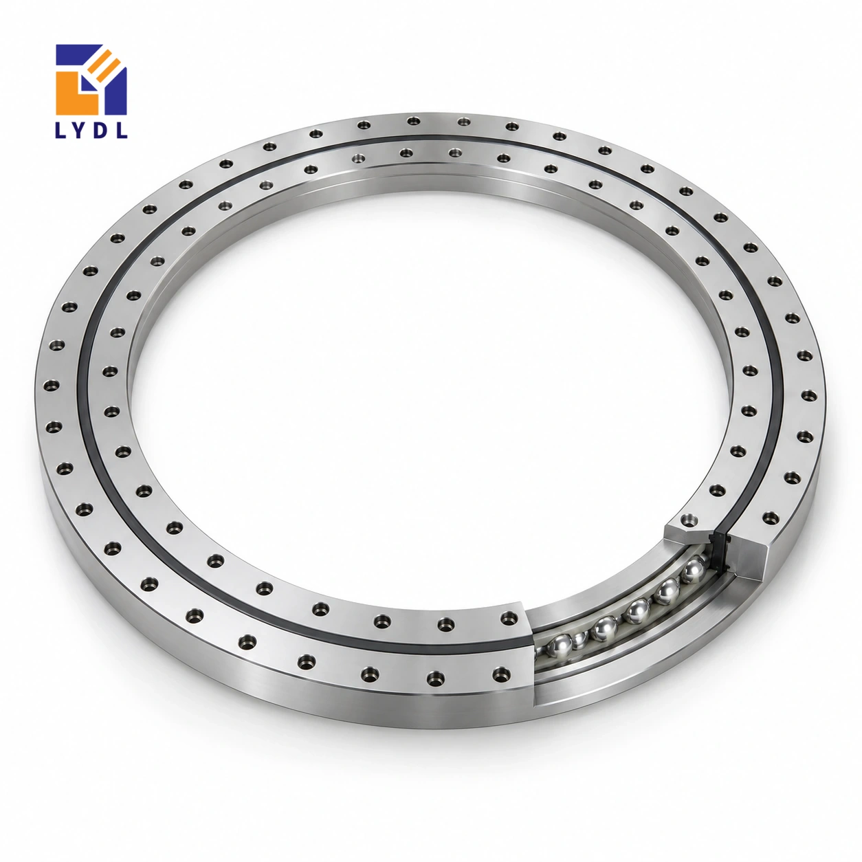
VU360680 is the largest VU reference in this requested set, using four-point contact balls without integral gear teeth. LYDL lists a 565 mm bore, 795 mm outside diameter and 79 mm overall height, with approximate reference mass 120 kg.
VU360680: current LYDL nominal table. Confirm the supplied configuration and limits by drawing.
VU specification tables · Family technical reference
| Bore (mm) | Outside (mm) | Height H (mm) | Mass ≈ (kg) |
|---|---|---|---|
| 565 | 795 | 79 | 120 |
| Outer PCD La (mm) | Inner PCD Li (mm) | Outer holes na | Hole dB (mm) | Secondary h (mm) |
|---|---|---|---|---|
| 755 | 605 | 30 | 22 | 72 |
The reference mass excludes the platform, adapters and drive equipment, so define which components are moved together during installation. Establish a clean supported staging area and a lift path that does not use seals, fittings or unapproved ring features as attachment points. Check access to the thirty-position outer connection before central equipment is installed. Handling and service planning are part of the machine arrangement, separate from determining its operating load capability.
The current mounting circles are 755 mm and 605 mm, with 22 mm hole diameter. Overall H is 79 mm, while h is 72 mm; use the correct surface definitions when building the axial stack.
Describe the time and environment between delivery and installation, including any unheated storage or exposed unloading stage. Agree preservation and packaging for that route rather than assuming a generic carton or crate illustration establishes protection. At assembly, identify stable staging support and the complete mass moved at each step. Keep central equipment clear until the inner connection has the access required by the approved sequence.
Once mounted, check the machine under defined conditions and retain that baseline for later maintenance. The published height supports layout work; it does not specify handling attachments or operating capacity.
Read VU360680 as a four-point contact ball reference with 565 mm bore, 795 mm outside diameter and 79 mm overall H. The separate h entry is 72 mm; use its labelled drawing feature rather than assuming it describes the whole assembly. The approximate listed mass is 120 kg and supports component handling information, not a payload rating. La = 755 mm locates the outer fixing circle; it is not the outside diameter. A connection also needs its hole form, screw engagement and locating features. Compare those items with the actual machine drawing before releasing mating parts. Values absent from the website row remain unresolved rather than becoming zero. The nominal table helps identify the intended geometry, while the agreed supply drawing defines the purchased execution.
Use the current LYDL overall H of 79 mm for this reference. The separate h entry is 72 mm and must retain its own feature label. Place both on the offered section with the mounting planes identified. A smaller secondary feature cannot be substituted for the complete ring height when setting the platform stack.
The nominal bore is 565 mm and the outside envelope is 795 mm. Add the real base, upper deck, adapters and locating shoulders around that ring. Check the working plane and service access as one assembly. This prevents a correct nominal dimension from being applied to the wrong surface or used without the surrounding stack that determines the machine layout.
The approximate 120 kg listed mass supports planning for receipt and installation of the component. Check the workshop route, package access and space above the seating. Ask for approved handling provisions for the supplied execution instead of selecting an unverified hole, edge or seal feature as a lifting point.
Show temporary support while the upper structure and separate transmission are fitted. Keep machined faces protected from loose hardware and uneven local support. Identify the component and accepted drawing revision before it becomes concealed in the machine. Handling information is part of a practical supply enquiry, while component mass provides no approved payload rating for the completed platform.
The outer attachment circle is 755 mm and the inner 605 mm, with thirty listed positions and a 22 mm hole entry. Confirm the actual hole form, screw seats, engagement and locating features from the offered drawing. Check access around the installed drive, guards and central services.
Review backing beneath the full annuli, including frame joints, pockets and access openings. Define the state in which seating geometry is inspected after fabrication. Follow the agreed assembly method. The ring should be secured to a prepared interface rather than used to pull a distorted flange into shape. A large support or substantial fastener count cannot replace review of the actual connection.
Show tooling and payload at their actual locations and heights. Include partial occupancy, loading actions and process forces during dwell. State angular movement, timing, acceleration and reversal with the moving mass distribution. A larger reference number does not settle an unspecified operating load or moment.
Draw the separate drive and identify its reaction path, including tension, contact or linkage forces where relevant. Show any holding restraint used during processing. Define the installed result at a working datum with a stated load and approach condition. The four-point ball arrangement, supporting plates, joints and transmission all contribute, so the actual offered execution needs assessment within that complete machine.
Send the mating sections, operating cases and inspection request together. Ask LYDL to identify the supplied configuration and applicable limits. Separate received-component checks from the completed-platform test and keep the support and load conditions with each result. Retain flange, fixture and drive revisions with commissioning information.
Discuss contamination, cleaning and idle storage when reviewing protection and service access. Request suitable shipment support and preserve identity after unpacking. The family picture and generic inspection montage cannot document testing of this individual supply. A future spare order should refer to the accepted drawing and operating record, allowing changes in tooling or duty to be evaluated explicitly.
VU300574 is the nearest smaller requested VU opening at 468 × 680 × 68 mm, compared with 565 × 795 × 79 mm here. Its twenty fixing positions differ from the thirty listed for VU360680. The outer/inner circles move from 640/508 mm to 755/605 mm, changing both mating patterns and the support required beneath them.
For a machine with a fixed working plane, compare the complete stack rather than reducing either overall H to its secondary h feature. Include the separate drive, guard and maintenance movements. If the larger opening is needed by central equipment, check the actual connector and removal route as well as running clearance.
The end of this requested VU list is not an automatic recommendation for an unspecified payload. Submit the real force locations and motion with the preferred geometry, then resolve the supplied execution and limits. Retain the accepted component, mating and drive revisions with the installation record so later spare orders preserve a reviewed machine configuration.
A large rotary handling platform is a representative use study. Supply maximum eccentric payload positions, horizontal forces and stop conditions together with the drive reaction and required stiffness.

Agree receiving identification, geometric acceptance and a supported functional check before transport. Discuss a rigid shipping base and moisture protection suited to the actual route and storage period.

Use the website H value of 79 mm. The 72 mm h entry describes a different drawing feature.
The current row gives 755 mm outside and 605 mm inside, with thirty outer positions and 22 mm hole diameter.
It describes the approximate bearing mass only. Add adapters, plates, drive parts and attached equipment when planning the actual lifted assembly.
It has no specified integral teeth. A separate transmission or drive interface must be designed and included in the load assessment.
Installation defines safe support, access and handling. Operating suitability requires the separate force, moment, duty and stiffness review of the supplied execution.
Compare roller principles through XU series and XSU range.
For VU360680, include the installation sequence, complete lifted mass and the governing operating-load diagram.