

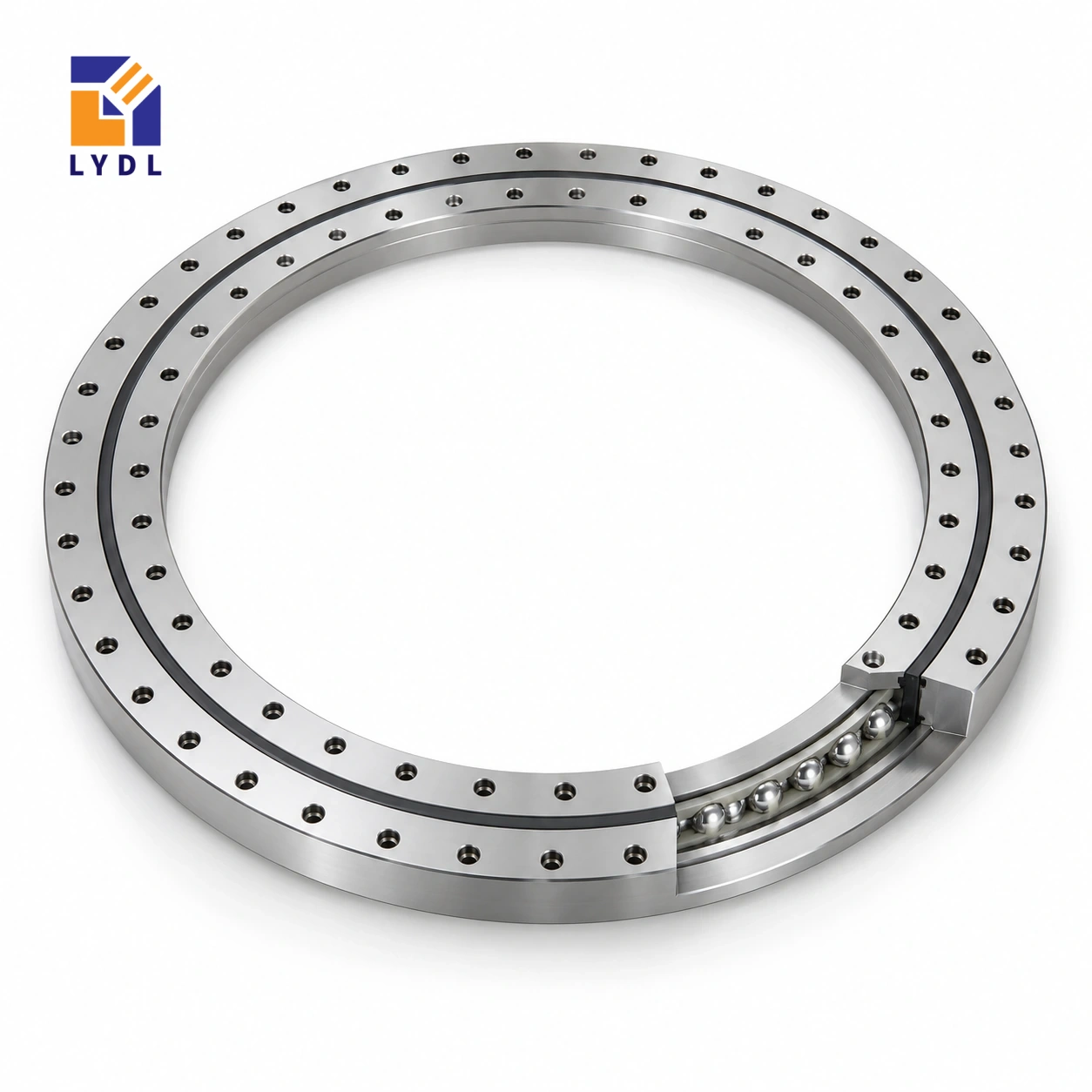
The VU300574 slewing bearing is an ungeared four-point contact ball reference with a 468 mm bore, 680 mm outside diameter and 68 mm overall height. Its twenty-position outer fixing pattern requires review with the supporting plate and separate drive.
VU300574: current LYDL nominal table. Confirm the supplied configuration and limits by drawing.
VU specification tables · Family technical reference
| Bore (mm) | Outside (mm) | Height H (mm) | Mass ≈ (kg) |
|---|---|---|---|
| 468 | 680 | 68 | 82 |
| Outer PCD La (mm) | Inner PCD Li (mm) | Outer holes na | Hole dB (mm) | Secondary h (mm) |
|---|---|---|---|---|
| 640 | 508 | 20 | 22 | 61 |
A large handling platform can experience horizontal forces far above the ring plane, generating moments that are not apparent in a payload-weight statement. Draw the platform, upright fixture and load application points in section. Include acceleration, braking and any manual or process force at height. The 640 mm and 508 mm fixing circles identify the connection geometry, but the plate and fastener system need their own assessment alongside the bearing execution.
The current table lists 22 mm fixing-hole diameter and a 61 mm h dimension distinct from the 68 mm total height. Keep shoulder and mounting-face definitions explicit to avoid shifting the platform working level.
A side force applied near the top of a frame should be located on the load sketch by both direction and height. Include guide reactions, transfer forces and foreseeable manual forces where relevant. Compare their moments with the gravity load at its eccentric position. For stopping, describe the platform motion and payload arrangement at the start of deceleration.
These cases can govern differently. Define the accepted loaded displacement at a useful equipment datum, while keeping the component receiving checks tied to the supplied bearing drawing.
Read VU300574 as a four-point contact ball reference with 468 mm bore, 680 mm outside diameter and 68 mm overall H. The separate h entry is 61 mm; use its labelled drawing feature rather than assuming it describes the whole assembly. The approximate listed mass is 82 kg and supports component handling information, not a payload rating. La = 640 mm locates the outer fixing circle; it is not the outside diameter. A connection also needs its hole form, screw engagement and locating features. Compare those items with the actual machine drawing before releasing mating parts. Values absent from the website row remain unresolved rather than becoming zero. The nominal table helps identify the intended geometry, while the agreed supply drawing defines the purchased execution.
The nominal 468 mm opening and 680 mm outside envelope should be placed on the actual platform section. Show any fixed central equipment, rotating tooling and services through their operating and maintenance movements. Include collars, connectors and the temporary route used for assembly. The ring bore does not alone define useful central space.
Set the working plane from the complete stack around the 68 mm overall H. Include adapters, seats and supporting plates. Check the sequence for installing the ring and upper structure, with a supported state for maintenance. A large nominal opening can still leave inner screws inaccessible if these surrounding parts are added without an access study.
Provide the payload and fixture locations with their radial and vertical offsets. Include process contact during dwell and partially occupied configurations. The largest centred mass may differ from the most important eccentric case. Keep force directions and application points in the operating description rather than reducing the duty to one weight.
The ring is ungeared, so add the transmission's own force path. A belt, wheel or linkage can introduce tension or contact reactions that the payload sketch omits. Describe any separate restraint used while processing. The four-point ball principle and approximate 82 kg component mass do not assign a permitted payload, moment or drive torque for this assembly.
The outer fixing circle is 640 mm and the inner 508 mm. Confirm the full offered hole form, seats, screw engagement and locating features at the twenty listed positions. A hole diameter and count do not specify the whole joint. Check angular orientation and tool access beside the drive and central equipment.
Review flange backing around pockets, service windows and frame joints. Define the geometry-check condition for the prepared seating and the agreed fastening method. Overall H is 68 mm, while the separate h value is 61 mm; retain both labels on the section. Do not use the lower value as the complete stack height or tightening as a means of correcting a distorted support.
State angular travel, acceleration, reversal and dwell with the moving mass distribution. If positioning or rocking movement matters, identify the observation datum, load and approach condition. A reading at a working point includes support plate deformation, joints, transmission and bearing behaviour. Ask for review of the actual offered execution against that system requirement.
Keep component receiving inspection separate from the installed observation. Agree each requested characteristic and method rather than relying on an unsupported precision adjective. At commissioning, retain the fixture and drive settings with the result. Later changes to tooling radius, process force or motion timing can then be assessed against a clear operating baseline.
Attach the mating drawings and duty to the enquiry, identifying interfaces that cannot change. Request handling information and packing suitable for the supplied ring. Protect the machined annuli and keep loose platform hardware separate. Do not use an unapproved local feature as a lifting point.
Describe contamination, cleaning, storage interval and service access when reviewing protection. Preserve identity and accepted drawing revision after receipt. The shared application and inspection images communicate possible tasks and general concepts; they are not evidence of this model's test or shipment. Link a future spare request to the accepted flange, transmission and operating record as well as VU300574.
VU360680 increases the opening from 468 to 565 mm and outside diameter from 680 to 795 mm. Current website H changes from 68 to 79 mm, while the separate h entries are 61 and 72 mm. The fixing count changes from twenty to thirty positions; both rows list a 22 mm hole entry. Equal hole size does not preserve the rest of the connection.
For a large platform, compare the central equipment, working plane and handling route on the complete sections. The larger envelope can answer an access requirement while changing the base and upper plate. Put the actual force application points and separate transmission on either proposal.
Ask for the individual offered drawing and operating assessment of the candidate that meets the machine constraints. Neither the higher model designation nor the approximate component mass establishes a permitted load. Keep the resolved height labels, support geometry and commissioning condition together so a future spare or duty change is checked against the actual accepted arrangement.
A material-transfer table carrying an upright frame is an illustrative case. Assess the most eccentric payload position and the emergency-stop event rather than only a balanced stationary condition.

Request dimensional checks and any agreed functional test under named support conditions. Plan transport restraint for the approximate 82 kg reference ring without loading vulnerable fittings or seal edges.

The current website lists 68 mm overall height. The separate h value is 61 mm and must keep its drawing meaning.
The listed circles are 640 mm and 508 mm, with twenty outer positions and 22 mm fixing-hole diameter.
That cannot be determined from weight alone. Provide horizontal forces, application heights, eccentricity and transient operating cases.
No integral teeth are specified for the VU family reference. The chosen separate drive and its reaction loads need layout and load review.
Use the agreed datum, support and fastening conditions. Compare like conditions rather than treating every free-ring and mounted reading as equivalent.
Compare roller principles through XU series and XSU range.
Send VU300574 with force heights, deceleration data and the complete flange cross-section.