

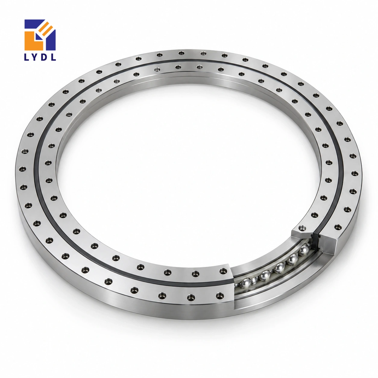
VU200405 is a gearless four-point contact ball slewing reference listed at 336 × 474 × 46 mm. Its thirty-position outer connection and broad central passage are useful layout features, with final selection dependent on the complete platform and duty.
VU200405: current LYDL nominal table. Confirm the supplied configuration and limits by drawing.
VU specification tables · Family technical reference
| Bore (mm) | Outside (mm) | Height H (mm) | Mass ≈ (kg) |
|---|---|---|---|
| 336 | 474 | 46 | 25 |
| Outer PCD La (mm) | Inner PCD Li (mm) | Outer holes na | Hole dB (mm) | Secondary h (mm) |
|---|---|---|---|---|
| 450 | 360 | 30 | 14 | 41 |
The XU160405 roller reference shares the same main envelope and fixing-circle values, but the contact arrangement differs. If the objective is retaining an existing table, compare shoulders, screw details and supplied clearance as well as the outside size. If the objective is improving a system requirement, define that requirement explicitly. A different bearing principle cannot compensate automatically for flexible plates, an unbalanced payload or an unsuitable drive bracket.
Use the listed 450 mm and 360 mm fixing circles to plan bolt and tool access around the central equipment. Confirm the 14 mm hole details and the complete inner pattern from the supplied drawing.
Record each approved tooling set with its attachment, mass distribution and process-force locations. Identify combinations that the machine permits during loading, maintenance and production. If tooling is later extended further from the axis, reassess the operating cases rather than assuming the original selection still applies. Compare commissioned behaviour under a repeatable setup so a support change can be distinguished from a changed load.
The reference envelope is useful for an interface study, while the completed machine needs its own controlled operating definition.
Read VU200405 as a four-point contact ball reference with 336 mm bore, 474 mm outside diameter and 46 mm overall H. The separate h entry is 41 mm; use its labelled drawing feature rather than assuming it describes the whole assembly. The approximate listed mass is 25 kg and supports component handling information, not a payload rating. La = 450 mm locates the outer fixing circle; it is not the outside diameter. A connection also needs its hole form, screw engagement and locating features. Compare those items with the actual machine drawing before releasing mating parts. Values absent from the website row remain unresolved rather than becoming zero. The nominal table helps identify the intended geometry, while the agreed supply drawing defines the purchased execution.
The nominal 336 mm bore, 474 mm outside diameter and 46 mm height also appear for XU160405 in the requested selection. This shared envelope can support a useful machine-layout comparison. It does not establish equivalent internal arrangement: VU uses four-point ball contact, while XU is a crossed-roller reference.
Compare the complete connection and section drawings, then request assessment against the actual equipment requirement. Resolve the offered execution and its applicable limits before considering interchange. The contact principle, supplied clearance and supporting structure affect the application discussion, and a dimensional match alone cannot establish equal stiffness, accuracy or permissible loading.
Draw fixed and rotating services through the 336 mm opening. Include connectors, hose restraints and the path used for maintenance. Determine which services remain stationary and which move with the table. A cable that clears the bore in operation may still be impossible to replace after the inner flange is secured.
Show the separate transmission beside the service layout. Check whether its bracket blocks fastener access or a removable central module. Establish the assembly sequence and a supported state for the table during bearing replacement. These details convert the nominal open centre into a practical equipment arrangement without assuming that an ungeared ring defines the rest of the drive.
List the approved tooling and payload combinations with their radial and vertical offsets. Include partial loading, operator actions and process reactions during dwell. State the motion schedule and moving mass distribution. Two configurations with the same total weight can impose different moments or inertia because the mass is placed differently.
For output behaviour, identify the working datum and the load and drive condition used for observation. The table plate, joints, transmission and bearing arrangement all contribute. Ask for the offered component to be reviewed within that complete machine. The approximately 25 kg ring mass helps plan handling but gives no permissible platform payload or guaranteed positioning result.
The 450 mm outer and 360 mm inner fixing circles list thirty positions with a 14 mm hole entry. Add the offered screw form, seats, engagement and locating features to both mating drawings. Review local backing and tool access around any pocket or motor support. Preserve overall H = 46 mm separately from h = 41 mm.
For the gearless drive, identify the actual belt, wheel or linkage and where its force acts. Include tension or contact reaction as relevant. Describe adjustment, guard opening and replacement access. A holding restraint used during processing belongs in the force-path drawing too. These inputs are necessary even when the same base envelope appears in another bearing family.
Attach the mating sections, duty and inspection request to the enquiry. Ask LYDL to identify the supplied execution and accepted revision. Define received-component checks separately from an installed test at the fixture. Record support, approach direction and load configuration so later observations use a comparable basis.
State contamination, cleaning and storage exposure when reviewing protection and service access. Keep loose brackets and fittings away from machined faces during shipment. Preserve the component and drive identities with the commissioning record. The shared pictures illustrate a family and general concepts; they cannot certify an individual test or establish a replacement relationship with XU160405.
XU160405 offers the same 336 × 474 × 46 mm nominal envelope but uses a crossed-roller arrangement. VU250433 is another ball-contact alternative with a 344 mm bore, 522 mm outside diameter and 55 mm H. A close opening in the latter conceals a wider outer package and taller stack, while the XU comparison changes internal principle within the same basic dimensions.
For a service-filled positioning table, overlay the actual connector routes and inner connection access. Keep the transmission and bracket in the drawing. Identify whether the machine requires the existing opening, working plane or outer support boundary to remain fixed. Those constraints determine which comparison is useful.
Resolve the complete offered section and connection before a replacement is accepted. Ask for assessment of the actual tooling, force locations and motion rather than adopting a general preference for one contact arrangement. Preserve the accepted identity and operating record; similar nominal envelopes cannot supply an order-specific inspection result or prove identical behaviour of the assembled table.
Record connector access with the actual central service bundle installed, including its restraints.
An assembly carousel with removable tooling is a representative study. Check each tooling configuration and include stationary process forces that may exceed the loads during indexing.

Agree receiving checks and an installed rotation comparison after fastening. Keep the ring supported during unpacking and prevent straps or hardware from contacting sealing edges.

The current LYDL row gives 336 × 474 × 46 mm and approximate mass 25 kg.
The cited references use 450 mm and 360 mm circles, but that match does not establish complete dimensional or functional interchangeability.
Thirty outer positions and 14 mm hole diameter are listed. Confirm both ring connections on the accepted drawing.
Assess the complete structure. Plate bending or a weak drive bracket may remain the governing source of displacement after a bearing substitution.
Describe the largest eccentric load and the strongest stopped process force among the approved configurations, not only the normal balanced setup.
Compare roller principles through XU series and XSU range.
For VU200405, include the retained machine interfaces and the governing tooling configuration.