

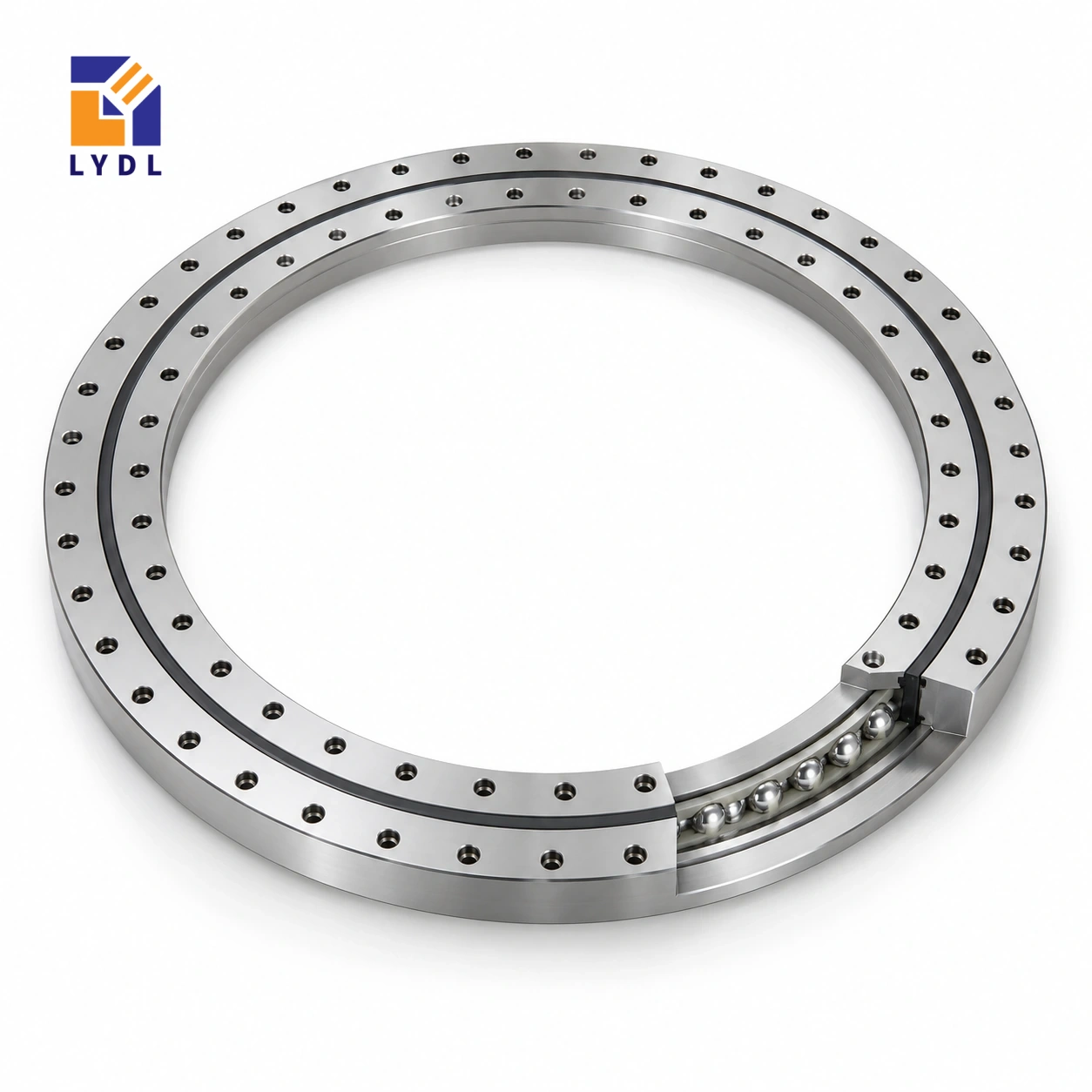
VU200260 is an ungeared four-point contact ball slewing reference with a 191 × 329 × 46 mm envelope. It uses a twenty-position outer connection in the current LYDL table and can be compared dimensionally with the XU160260 roller reference.
VU200260: current LYDL nominal table. Confirm the supplied configuration and limits by drawing.
VU specification tables · Family technical reference
| Bore (mm) | Outside (mm) | Height H (mm) | Mass ≈ (kg) |
|---|---|---|---|
| 191 | 329 | 46 | 15 |
| Outer PCD La (mm) | Inner PCD Li (mm) | Outer holes na | Hole dB (mm) | Secondary h (mm) |
|---|---|---|---|---|
| 305 | 215 | 20 | 14 | 41 |
The shared basic envelope with XU160260 is useful when investigating whether an existing machine layout could accommodate another bearing principle. It does not establish equal stiffness, clearance or friction. Write down the reason for the proposed change, such as a measured displacement problem or an operating requirement, then compare the actual offered executions. Without that requirement, a dimensional match can encourage a replacement that leaves the original machine problem unresolved.
The listed fixing circles are 305 mm and 215 mm with 14 mm hole diameter. Confirm the complete mounting and centring drawing and inspect the supporting faces before fastening the ring.
Describe the existing symptom before proposing a different contact arrangement. Lost movement on reversal, excessive loaded displacement and unexpected rotation resistance require different observations. State the measuring point, direction, load and assembly condition for each. Examine the mating plates and drive support in the same review.
A different ring execution may be useful, but it should not be presented as a cure for an unmeasured system problem. Retain the accepted interface drawing and the agreed functional requirement together so the replacement can be judged against a clear objective. If clearance is central to the comparison, ask how it will be defined and checked for the offered assembly. Record temperature, support and measurement location where these form part of the agreed procedure.
Do not compare an unloaded reading from one execution with a loaded displacement from another and call the difference a bearing improvement. Use equivalent conditions and keep the machine-level objective distinct from the component measurement.
Read VU200260 as a four-point contact ball reference with 191 mm bore, 329 mm outside diameter and 46 mm overall H. The separate h entry is 41 mm; use its labelled drawing feature rather than assuming it describes the whole assembly. The approximate listed mass is 15 kg and supports component handling information, not a payload rating. La = 305 mm locates the outer fixing circle; it is not the outside diameter. A connection also needs its hole form, screw engagement and locating features. Compare those items with the actual machine drawing before releasing mating parts. Values absent from the website row remain unresolved rather than becoming zero. The nominal table helps identify the intended geometry, while the agreed supply drawing defines the purchased execution.
This VU reference has the same nominal 191 mm bore, 329 mm outside diameter and 46 mm height as XU160260 in the requested group. The VU arrangement uses four-point ball contact, while XU is a crossed-roller family. Matching three dimensions is therefore useful for a layout comparison but does not establish equivalent internal execution or installed performance.
Compare the complete drawings, connections and application requirements before recording a replacement decision. Ask for the actual offered clearance, limits and relevant inspection information. Do not transfer a precision, stiffness or permissible-load statement from one contact arrangement to the other on the strength of a shared envelope.
Draw the 191 mm central opening with any fixed body, service route or rotating fixture stem. Include connectors and the temporary space needed for assembly. The drive is separate because the ring is ungeared. Place that transmission and its bracket on the same layout, with force application points visible.
If a belt or contact wheel is proposed, describe its tension or contact reaction. If a linkage is used, show the relevant geometry through the motion. The resulting forces may differ even when the desired output torque is the same. Include adjustment, guard opening and removal access so the selected arrangement remains serviceable after the platform is installed.
List the tooling and payload at their actual radii and heights. Show normal loading and unloading actions, including contact with guides or stops. State angular travel, acceleration, reversal and dwell. A short move may still involve a different demand from stationary holding, so keep those phases identifiable in the operating schedule.
If a separate restraint acts during processing, indicate where it connects to the platform and base. Define the required installed behaviour at a named working datum. The support, fasteners, drive and bearing arrangement all contribute to that result. The approximate 15 kg component mass does not define the permissible workpiece weight or an automatic advantage over the similar-sized XU reference.
The outer fixing circle is 305 mm and the inner is 215 mm, with twenty listed positions. Add the offered hole form, screw engagement, seats and locating details to the mating drawings. Check that the actual support backs both annuli and that tools can reach every required position with the drive present.
Overall H is 46 mm and the separate h entry is 41 mm. Preserve their labels and use the offered section to identify the associated surfaces. Do not choose the smaller figure as the complete stack height. Inspect the prepared seating under a defined support condition and follow the agreed fastening method instead of using the ring to correct an uncertain interface.
Provide the equipment section, duty and inspection request with the enquiry. Ask LYDL to identify the supplied execution and accepted drawing revision. Separate component receiving checks from the installed platform observation, recording the conditions for both. Keep the drive and fixture revisions linked to the bearing identity.
Describe contamination, cleaning and expected storage when reviewing protection and service access. Pack the ring away from loose brackets and fasteners and preserve machined faces during handling. The shared images explain family and application context; they do not document testing of VU200260 or establish interchange with XU160260. A future spare order should refer to the accepted configuration.
XU160260 matches the 191 × 329 × 46 mm nominal envelope of this VU row, while VU200220 offers the smaller 138 × 302 × 46 mm layout. Those two comparisons answer different questions: XU changes contact principle within a familiar envelope, and the other VU changes geometry within the ball-contact group.
Draw the actual fixture and external transmission on the preferred candidate. Resolve locating shoulders, hole forms, service features and the supplied clearance individually. A shared bore, outside diameter and height cannot establish a replacement decision. Conversely, a different envelope can sometimes be accommodated by redesign, but that redesign needs its own support and access review.
State what the machine must achieve at the working datum and under which load. This gives LYDL a meaningful basis for an offer and prevents a geometric comparison becoming an unsupported claim about roller-versus-ball performance. Keep the accepted section and operating conditions with the component identity so later spare orders preserve the reviewed configuration.
A rotary handling platform with an off-axis gripper is an illustrative case. Include gripper reach and the horizontal force during acceleration, as well as payload weight.

Request dimensional checks and the agreed running assessment for the actual supplied configuration. Avoid shipping restraints that pull against seals or unapproved protruding fittings.

The VU reference uses four-point contact balls. XU160260 is a different, crossed roller arrangement with the same basic reference envelope.
The current website gives 191 mm bore, 329 mm outside diameter and 46 mm overall height, with approximate mass 15 kg.
The listed circles are 305 mm and 215 mm. Twenty outer positions and 14 mm hole diameter are provided.
Define the actual system requirement or measured problem, then review the supplied configuration and mating structure against it.
An off-axis payload and horizontal acceleration can generate moments at the bearing plane. Weight without force location does not describe those effects.
Compare roller principles through XU series and XSU range.
If replacing a roller arrangement, send LYDL the observed issue and full interface drawing with VU200260.