

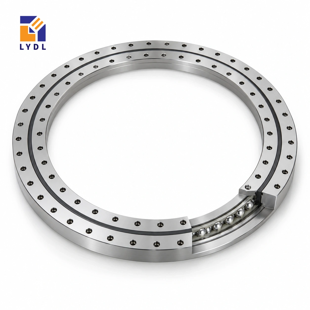
The VU200220 slewing bearing is a four-point contact ball reference without gear teeth. LYDL lists a 138 mm bore, 302 mm outside diameter and 46 mm overall height, providing a different package from the nearby VU200260 model.
VU200220: current LYDL nominal table. Confirm the supplied configuration and limits by drawing.
VU specification tables · Family technical reference
| Bore (mm) | Outside (mm) | Height H (mm) | Mass ≈ (kg) |
|---|---|---|---|
| 138 | 302 | 46 | 16 |
| Outer PCD La (mm) | Inner PCD Li (mm) | Outer holes na | Hole dB (mm) | Secondary h (mm) |
|---|---|---|---|---|
| 270 | 170 | 10 | 18 | 41 |
VU200220 has ten outer fixing positions and a 270 mm outer circle, whereas VU200260 lists twenty and a 305 mm circle. Both show a 46 mm height, but their bores and support layouts differ. For a replacement study, identify which machine interfaces are fixed constraints and compare those features first. A common prefix or equal height cannot establish that the existing flange, pilot or load path will suit the second model.
The inner fixing circle is listed as 170 mm and the hole diameter as 18 mm. Check the full ring patterns, screw seats and available plate material around the connection before approving the housing.
Overlay the proposed ten-position outer pattern on the existing base, including unused holes, dowels and reliefs. Check the remaining material around each attachment rather than counting aligned positions alone. If an adapter is considered, show where it provides location and how forces pass through both of its connections. Preserve enough room to tighten and remove screws after the drive is installed.
The ten-position reference does not establish a permissible payload; it identifies geometry that must be assessed with the complete support and operating duty.
Read VU200220 as a four-point contact ball reference with 138 mm bore, 302 mm outside diameter and 46 mm overall H. The separate h entry is 41 mm; use its labelled drawing feature rather than assuming it describes the whole assembly. The approximate listed mass is 16 kg and supports component handling information, not a payload rating. La = 270 mm locates the outer fixing circle; it is not the outside diameter. A connection also needs its hole form, screw engagement and locating features. Compare those items with the actual machine drawing before releasing mating parts. Values absent from the website row remain unresolved rather than becoming zero. The nominal table helps identify the intended geometry, while the agreed supply drawing defines the purchased execution.
The 138 mm bore and 302 mm outside diameter should be shown together on the fixture section. A narrow central stem may fit through the opening while the surrounding annular package sets the base footprint. Include collars, fittings and the route used to assemble the stem. The useful opening is an installed-space question, not simply a single table entry.
Place the working plane relative to the 46 mm overall height, including every plate and adapter. Check the available backing under both attachment zones. A compact fixture can become difficult to assemble if the drive or central stem blocks the inner fasteners. Establish the sequence and tool routes before fixing the plate design.
The nominal connection uses a 270 mm outer circle and 170 mm inner circle, with ten listed positions and an 18 mm hole entry. Keep the hole label and full form on the offered drawing. A clearance diameter alone does not define the screw, seat, engagement or locating method.
Show the real flange sections behind the pattern, including pockets and drive-bracket connections. Confirm angular orientation where access is constrained. Define the condition used to inspect the prepared seating and follow an agreed assembly method. Neither a relatively large hole nor a small position count establishes connection capacity without the rest of the joint and supporting structure.
List the moving fixture, part and any clamp with their radial and vertical positions. Include operator loading actions and process forces during dwell. A total mass placed on the axis can conceal the moment created by the actual workpiece arrangement. Describe the permitted tooling variants and any partial occupancy.
The four-point contact ball principle does not supply a numerical clearance, stiffness or accuracy for the offered component. Ask for review against the real duty and define the required output at a useful fixture datum. That observation includes the base, plates, joints and transmission. The approximate 16 kg ring mass is component-handling information and must not be used as a payload rating.
Draw the proposed drive in its working and service states. Identify where force is applied to the rotating part and how the bracket reacts into the base. If belt tension or friction contact is involved, include it in the load description. An ungeared ring does not determine those forces or supply an integral ratio.
For indexing, state travel, acceleration, reversals and dwell timing with the moving mass distribution. Specify holding during processing separately from motion. Check that the bracket and guard leave access to the connection and confirmed service features. This lets the component and equipment review address a defined assembly instead of an abstract torque requirement.
Request the offered LYDL drawing and applicable execution with the quotation. Agree received-component checks by characteristic and method. For the completed fixture, choose a repeatable load and approach condition, and record the observation datum. Keep those records distinct so free-ring inspection is not mistaken for loaded machine performance.
State the actual dust, liquids, cleaning and storage environment when discussing protection. Preserve machined faces and identity through shipment, separating loose fixture hardware. Retain the accepted support and drive revisions with the bearing record. If the fixture overhang or motion schedule later changes, assess it against that configuration rather than assuming the unchanged model number settles the revised duty.
VU200260 retains the listed 46 mm height but changes the bore from 138 to 191 mm and outside envelope from 302 to 329 mm. Its twenty fixing positions and 14 mm hole entry also differ from the ten positions and 18 mm entry here. A familiar H therefore does not preserve the mating pattern or the available support annulus.
For the compact offset-loaded fixture, place the real stem and tool on both candidate sections. Determine whether a larger opening solves access or simply changes the flange. The drive bracket and screw withdrawal paths need to be represented in either layout. An unchanged workpiece position can still load the two surrounding structures differently if their backing changes.
Choose a candidate by explicit machine constraints and ask for its supplied ball-contact execution and application review. The lower approximate mass of VU200260 in the listing does not rank payloads or indicate equivalent internal behaviour. Preserve the selected ring, flange and drive identities with the receiving and commissioning records, allowing a future change to be assessed against a clear baseline.
A material-handling swivel with a compact centre passage is a representative case. Include eccentric payload positions and the bracket reactions from the separate drive.

Specify checks at the relevant locating and mounting surfaces. Protect machined seats from pallet fittings and keep all loose attachment hardware packaged separately.

The current LYDL row lists ten outer positions. VU200260 is the nearby reference that lists twenty.
The website lists 138 × 302 × 46 mm, with approximate reference mass 16 kg.
Yes, those nominal circles are listed for this model. Check the complete hole count, screw geometry and locating details against the supplied drawing.
No integral teeth are specified in the VU reference. The machine needs a separately designed drive arrangement.
No. Their bores, outside diameters and connection patterns differ, and functional compatibility also depends on the accepted execution and operating loads.
Compare roller principles through XU series and XSU range.
Provide VU200220 with the existing flange constraints and the payload positions across the transfer cycle.