

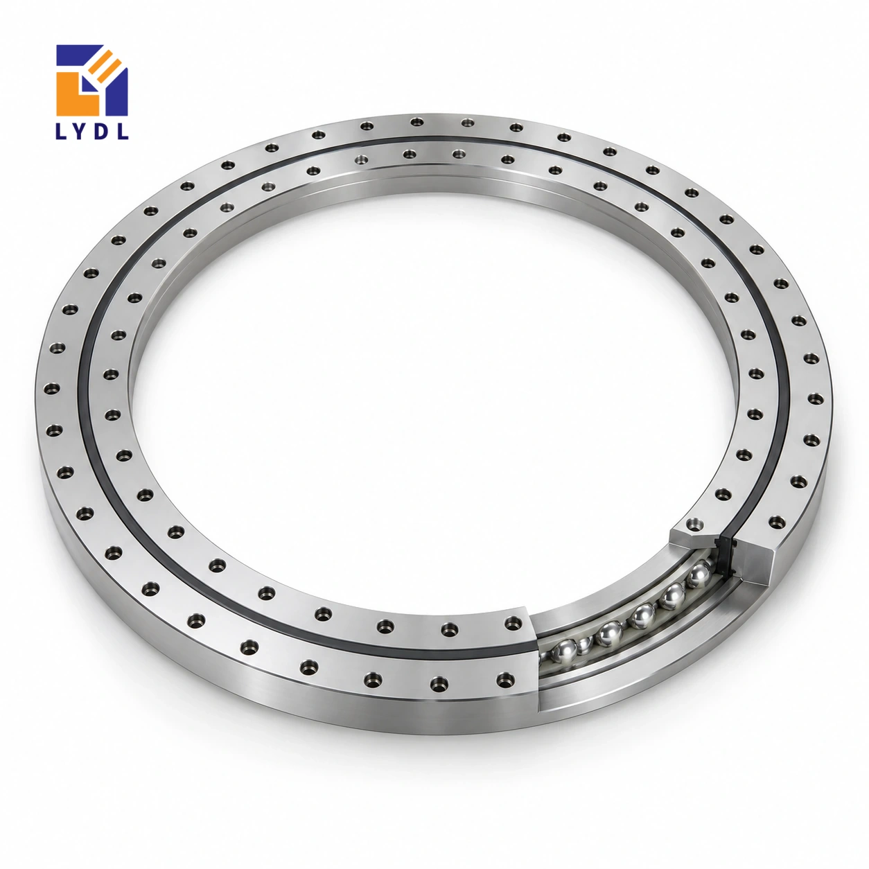
The VU140325 gearless slewing reference is a four-point contact ball arrangement measuring 270 × 380 × 35 mm. It combines a substantial centre opening with a shallower section than VU250380, despite the close bore dimensions of those two references.
VU140325: current LYDL nominal table. Confirm the supplied configuration and limits by drawing.
VU specification tables · Family technical reference
| Bore (mm) | Outside (mm) | Height H (mm) | Mass ≈ (kg) |
|---|---|---|---|
| 270 | 380 | 35 | 12 |
| Outer PCD La (mm) | Inner PCD Li (mm) | Outer holes na | Hole dB (mm) | Secondary h (mm) |
|---|---|---|---|---|
| 360 | 290 | 24 | 11 | 30 |
VU140325 has a 270 mm bore and 380 mm outside diameter, whereas VU250380 is listed at 275 mm and 485 mm with a 55 mm height. The small difference in bore conceals a major difference in the rest of the package. Check the available annular support and installation stack before reviewing operating loads. Neither the close bores nor the larger bearing mass establish that one reference can replace the other.
The current row lists twenty-four outer positions, 360 mm and 290 mm fixing circles and 11 mm hole diameter. Confirm the complete inner attachment and locate the support shoulders on the accepted section.
Mark the product-transfer level and the fixed feed centreline on the equipment section. Then place the bearing and both plates relative to those datums. Check access for replacing the feed component without disturbing the rotary connection. A reference with a nearby bore but a taller package may shift the working level even if the centre passage remains usable.
Include guide forces and operator adjustment loads at their actual heights. This helps assess the complete packaging station instead of selecting solely on bore clearance.
Read VU140325 as a four-point contact ball reference with 270 mm bore, 380 mm outside diameter and 35 mm overall H. The separate h entry is 30 mm; use its labelled drawing feature rather than assuming it describes the whole assembly. The approximate listed mass is 12 kg and supports component handling information, not a payload rating. La = 360 mm locates the outer fixing circle; it is not the outside diameter. A connection also needs its hole form, screw engagement and locating features. Compare those items with the actual machine drawing before releasing mating parts. Values absent from the website row remain unresolved rather than becoming zero. The nominal table helps identify the intended geometry, while the agreed supply drawing defines the purchased execution.
The 270 mm bore, 380 mm outside diameter and 35 mm overall height may be considered for an annular fixture around stationary equipment. Draw that equipment with its collars, connectors and service movements. Show the rotating flange and any drive attachment through the intended motion. The bore alone does not establish useful assembly clearance.
Set the working plane using the complete plate stack. Include screw seats, adapters and locating shoulders, then check how tools reach the inner connection. A low ring can still require a substantial supporting plate or an awkward maintenance sequence. Resolve those parts of the equipment layout before treating the nominal envelope as a finished table design.
State the actual speed or move timing required by the machine rather than inferring suitability from a general slow-positioning description. Include angular travel, dwell and reversal with the mass distribution. The supplied execution needs review against that duty; the four-point ball family does not assign an undocumented speed or life limit.
Show force locations for the payload, clamps and process contact. A centred part and an offset tool can create different operating cases even if their total weight is unchanged. Define the required behaviour at the fixture's working datum. The base, joints, plates and transmission contribute to that result, so an application assessment needs more than the bearing dimensions.
Draw the proposed belt, wheel, linkage or other motion input and identify its reaction path. The ring has no integral gear, which leaves the transmission concept open but also leaves its forces to be specified. Include tension, contact or linkage reactions relevant to the actual arrangement.
Check adjustment and replacement space with the fixture and central equipment installed. Identify any restraint used for holding during a process operation. Keep that case separate from acceleration. A model enquiry with a torque number but no force location or bracket section would omit important support information. Provide the layout so the proposed component and surrounding structure can be reviewed coherently.
The reference lists twenty-four positions, with outer and inner circles of 360 mm and 290 mm and an 11 mm hole entry. Confirm the full offered hole form, engagement and locating details. A circle and a count identify a pattern but do not fully specify its joint.
Review actual backing around pockets and frame connections. Check angular orientation and tool access after guards are installed. Keep overall H = 35 mm distinct from the separate h = 30 mm feature in the section drawing. Inspect the prepared seating in a defined condition and follow the accepted fastening method. The ring should not be used to force an uncertain pilot or distorted flange into place.
Submit the fixture drawing, operating cases and requested quantity. Ask for the supplied configuration and applicable inspection scope. Agree component checks separately from the completed-machine observation, including the load and support condition. Retain the accepted drawing with the drive and platform revisions for repeat orders.
Explain particles, cleaning and idle storage when reviewing protection. The approximately 12 kg mass is useful for component handling and is not a payload rating. Protect machined surfaces and separate loose fixture hardware in shipment. Generic application and packaging photographs provide context, while any requested evidence for this exact supply needs to be tied to the actual ordered component.
VU200405 has a 336 mm bore and 474 mm outside envelope with 46 mm H, compared with 270 × 380 × 35 mm here. Its thirty-position, 14 mm-hole connection differs from the twenty-four-position, 11 mm-hole entry of this row. Enlarging the opening therefore changes the platform stack and attachment study together.
If the central equipment is the main constraint, compare its collars and removal path within both openings. If working height is fixed, include the possible adapter and plate changes before choosing the larger reference. Show the separate drive's force location on each proposal, keeping the actual fixture overhang and duty unchanged unless the machine itself is revised.
These nominal values can identify an appropriate layout enquiry. They do not rank the supplied clearances, permissible loads or installed results. Ask for the offered execution and application assessment against the intended positioning schedule. Retain the chosen flange, drive and fixture revisions so the eventual spare can be ordered from a defined configuration rather than a remembered envelope.
A packaging station rotating around a fixed feed path is one design example. Study feed alignment, edge forces during adjustment and the actual loading during indexed motion.

Identify the faces that establish the working level and request measurements against that datum. Provide separators so the mounting surfaces remain protected from adjacent shipment items.

Their bores are close, but outside diameters and heights differ considerably: 380 × 35 mm versus 485 × 55 mm.
Use the current LYDL overall-height value of 35 mm. The separate h entry is 30 mm.
Twenty-four positions on a 360 mm circle, with 11 mm hole diameter. The inner fixing circle is 290 mm.
No. The approximate 12 kg reference mass describes weight, not an allowable force, moment or service life.
Show feed alignment, working height, actual support width and the complete drive envelope, plus loads during motion and dwell.
Compare roller principles through XU series and XSU range.
Send the required working height and available support-ring width when enquiring about VU140325.