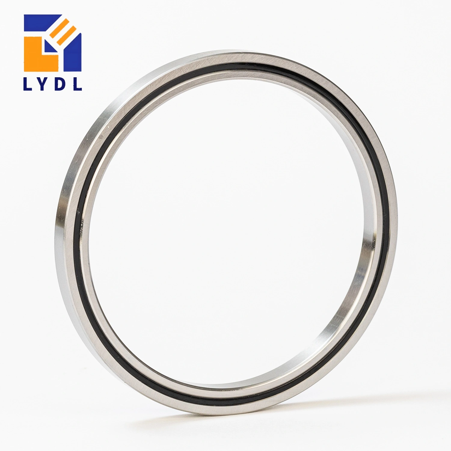
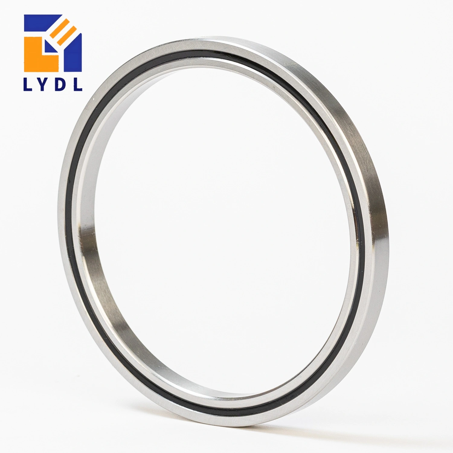
The RAU9005C0 cross roller bearing reference combines a 90 mm bore with a 101 mm outside diameter and 5 mm width. It can be considered for a shallow peripheral stage where a broad hub or instrument mount needs limited axial space. Supporting and protecting the bearing still require their own room. THK lists an open C0 configuration with normal grade 0 accuracy for this thin family. [3, 4]
Review the cross roller bearing selection guide together with the complete hub and enclosure section. THK’s RAU9005 row provides the documented reference for this envelope. A 90 mm counterpart was not verified in the cited IKO standard CRBT range. Assess any supplier-specific alternative from its drawing and configuration, rather than extrapolating features from a model code. [2, 3]RAU9005C0 product view; configuration follows the agreed drawing.
RAU9005C0 Dimensions and Reference Ratings
THK RAU9005C0 reference data [3]
Parameter
THK RAU9005C0
Bore d
90 mm
Outside diameter D
101 mm
Width B / B1
5 mm
Radial section (D – d) / 2
5.5 mm
Roller pitch circle dp
94.7 mm
Minimum chamfer r
0.15 mm
Shaft shoulder ds (maximum)
92.5 mm
Housing shoulder Dh (minimum)
97 mm
Dynamic radial load rating C
3.19 kN
Static radial load rating C0
6.03 kN
Reference mass
56 g
Lubrication holes
2 x Ø1 mm
Reference seals
Open; seals not supported
Reference clearance / accuracy
C0 / normal grade 0
The THK reference gives C 3.19 kN, C0 6.03 kN and mass 56 g. The radial section is only 5.5 mm despite the 90 mm bore. Evaluate the hub, flange and bearing under the actual loading and moment offsets. These source figures do not establish a general payload rating or the rigidity of a finished stage. The agreed LYDL drawing should identify supply configuration and the inspection limits required for the order. [3, 6]
Structure and Mounting Diagram
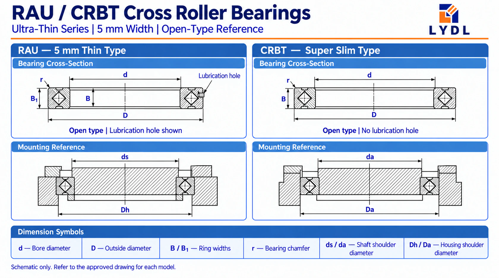
The RAU schematic symbols correspond here to d = 90 mm, D = 101 mm and B/B1 = 5 mm. THK lists dp = 94.7 mm, r minimum 0.15 mm, ds maximum 92.5 mm and Dh minimum 97 mm. The lubricant detail is two Ø1 mm holes. Use that panel for this reference; the adjacent CRBT illustration shows a separate construction and does not verify a catalogue CRBT905A equivalent. [2, 3]Separate open-type RAU and CRBT references; choose the matching panel.
Review a Broad Hub with a Narrow Bearing Section
The hub can occupy much more axial space than the bearing and can carry components at a considerable offset. Show those interfaces in the load path. A broad mounting face does not necessarily provide continuous support at the bearing seat, especially if recesses or access windows interrupt it. Include their position in the section and support review.
The CRBT / RAU ultra-thin bearing range offers a view of the 5 mm size group. For the 90 mm layout, retain the actual 101 mm housing constraint in the comparison. Adding an adapter or larger cover can remove the intended packaging benefit. Compare the finished assembly dimensions and required servicing space rather than the catalogue envelope alone.
Configuration, Accuracy and Replacement Review
The official thin RAU table specifies C0 and normal grade 0, with no seals supported. A standard P5 configuration cannot be inferred from the original candidate suffix. If the stage needs a tighter numerical limit, define it through the measured surface, datum, fixture and acceptance value. Record the reviewed special requirement explicitly in the LYDL supply agreement. [3]
Review the RAU series size range if an 8 mm bearing is feasible. RAU9008 measures 90 × 106 × 8 mm, with a different shoulder and lubricant arrangement. Moving to it changes both the seat diameter and axial stack. Identify which hub and enclosure features would need revision before proposing it as a same-bore alternative.
Plan Cover Clearance and Service Access Together
A close external cover can help protect an open bearing but needs enough clearance throughout the required operation. State the materials and temperature conditions of the hub and housing where they influence the layout. Check the assembly under those conditions using an agreed method instead of assuming the room-temperature nominal section describes every clearance.
The CRBH / CRBHV bearing options provides other reference constructions when space allows a larger section. Carry the same enclosure-access and operating-condition requirements into that comparison. A suitable proposal should address the mounting interface and maintenance route as well as reference ratings. Keeping those requirements visible prevents a component change from creating an inaccessible service point.
Application Selection Examples
Optical positioning: review a shallow instrument stage. Include hub offset, optical reference and enclosure clearance in the motion requirement.
Laboratory automation: consider a peripheral measurement platform. State cleaning exposure, service access and any stationary contact load.
Semiconductor equipment: assess a compact rotary support. Confirm contamination controls, lubricant suitability and actual operating conditions.
Compact robotics: evaluate an annular accessory axis. Include the carried assembly’s lever arm and cable forces beyond the bearing seat.
Compact rotary-axis concepts; operating suitability needs an assembly review.
Verify the Operating Clearance at the Completed Stage
For THK’s mounting reference, compare the support to ds ≤ 92.5 mm and Dh ≥ 97 mm. The final fit tolerances and seating-face requirements need separate definition. Allow appropriate corner clearance for the 0.15 mm minimum chamfer reference. Show the locating face, flange contact and any recesses so the retained ring is supported according to the reviewed design. [3, 5]
Identify the two Ø1 mm lubrication holes and plan access after the cover is installed. Keep that route distinct from cleaning drains, cable openings and fixing holes. Define the lubricant and maintenance method from the actual supply and operating conditions. The source schematic should explain the design, while an approved assembly drawing controls the manufactured interface.
Check rotation after bearing retention, then after installing the hub attachments, drive and cover. Verify the defined operating clearances and repeat the relevant motion measurement at the same datum. If temperature is an acceptance condition, include it in the test plan. A staged record helps trace rubbing, resistance or alignment changes to the relevant assembly step.
Inspection and Export Packing
Agree bearing geometry and clearance checks at identified datums. A stage-level accuracy requirement needs its own test radius and operating conditions.
Keep loose accessories off the locating faces and support the thin ring individually. Label the 90 × 101 × 5 mm configuration and any approved custom feature. Confirm records and corrosion protection; the montage is an explanation of methods.Inspection and protective packing illustration; agreed records define the actual shipment.
RAU9005C0 FAQ
1. Does the 90 mm bore imply a large load-carrying section?
No. This reference has a 101 mm outside diameter, giving a radial section of 5.5 mm and a 5 mm axial width. Evaluate the actual force and moment conditions along with hub and housing support. Bore size alone is not a rigidity or payload rating.
2. Which dimensions distinguish RAU9005 from RAU9008?
RAU9005 has a 90 × 101 × 5 mm envelope; RAU9008 has 90 × 106 × 8 mm. Their seat diameter, width, mounting support and lubrication details differ. A transition requires an interface review rather than a change of designation on the same housing drawing.
3. How should enclosure clearance be checked?
Define the cover, hub materials and relevant operating conditions, then verify the required clearances on the completed arrangement. Use the approved method and datum. A nominal room-temperature section is a starting point, not proof that a close cover remains clear throughout service.
4. Is the lubricant access still needed under an external cover?
It must remain compatible with the agreed maintenance method. The THK reference shows two Ø1 mm lubrication holes, so coordinate their housing access with the cover. Identify which features provide lubrication instead of treating any opening as an interchangeable service route. [3]
5. What should I send when replacing an existing 90 mm thin bearing?
Provide the full original identifier, supplier drawing, envelope, clearance and accuracy requirement. Include lubrication access and the retained assembly section. These details allow a comparison with RAU9005C0 while keeping any supplier-specific designation separate from the verified THK reference. [3]
Request a Drawing and Quotation
Provide the hub and cover section, loading offsets, operating conditions and maintenance route. Identify RAU9005C0 as the reference and state any special numerical acceptance. You can contact LYDL for a reviewed LYDL configuration drawing, quotation and export plan that address the complete shallow-stage assembly.