

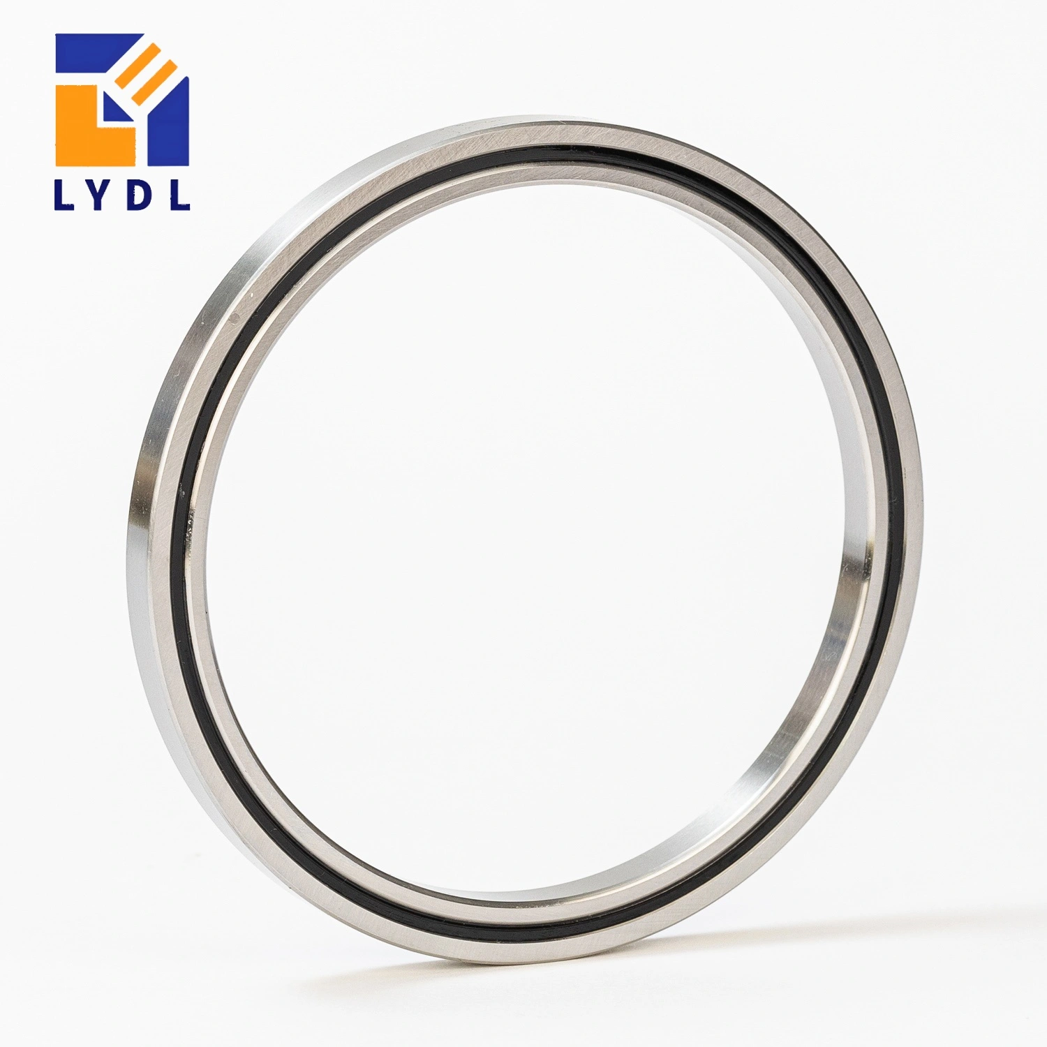
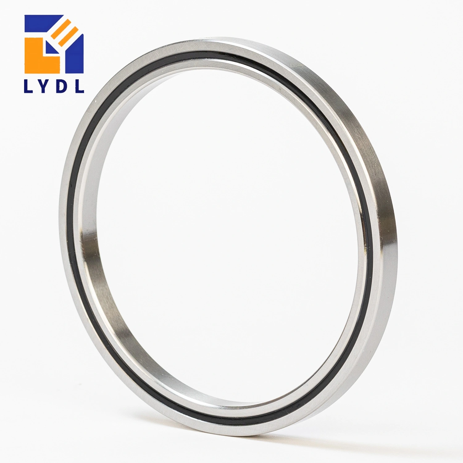
The RAU7008 cross roller bearing uses a 70 × 86 × 8 mm boundary envelope. Its reference construction combines integral inner and outer rings with crossed cylindrical rollers, making it a candidate for a compact rotary stage where either ring rotates. The design belongs to THK’s RA-compatible range rather than the smaller-section RAU7005 family. [1, 2]
An optical stage needs its bearing, encoder and working element to form one controlled axis. The 70 mm bore can help accommodate a hollow shaft or mounting hub, but alignment depends on the full structure. Begin with the cross roller bearing selection guide, then specify the important optical surface and the permitted movement at that surface.
| Parameter | THK RAU7008 |
|---|---|
| Bore d | 70 mm |
| Outside diameter D | 86 mm |
| Width B / B1 | 8 mm |
| Radial section (D – d) / 2 | 8 mm |
| Roller pitch circle dp | 77 mm |
| Minimum chamfer r | 0.5 mm |
| Shaft shoulder ds (maximum) | 73.5 mm |
| Housing shoulder Dh (minimum) | 80.5 mm |
| Dynamic radial load rating C | 5.98 kN |
| Static radial load rating C0 | 9.80 kN |
| Reference mass | 0.1 kg |
| Lubrication holes | 4 x Ø1.5 mm |
For the THK RAU7008 reference, dynamic radial rating C is 5.98 kN and static radial rating C0 is 9.80 kN. The listed mass is 0.10 kg. Keep these entries associated with this model. The stage payload, reaction at a mirror mount and transient drive forces must be converted into the relevant bearing loads before those catalogue ratings can support a selection decision. [2, 6]
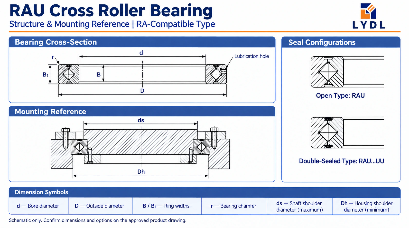
Read the structure diagram as a symbol key: d = 70 mm, D = 86 mm and B/B1 = 8 mm. The roller pitch circle is 77 mm. Shaft shoulder ds is a maximum of 73.5 mm, while housing shoulder Dh is a minimum of 80.5 mm. Neither shoulder value is a fit tolerance or a fixing-hole circle. The open and sealed views show family options; their internal profiles are illustrative, not machining dimensions. [2]
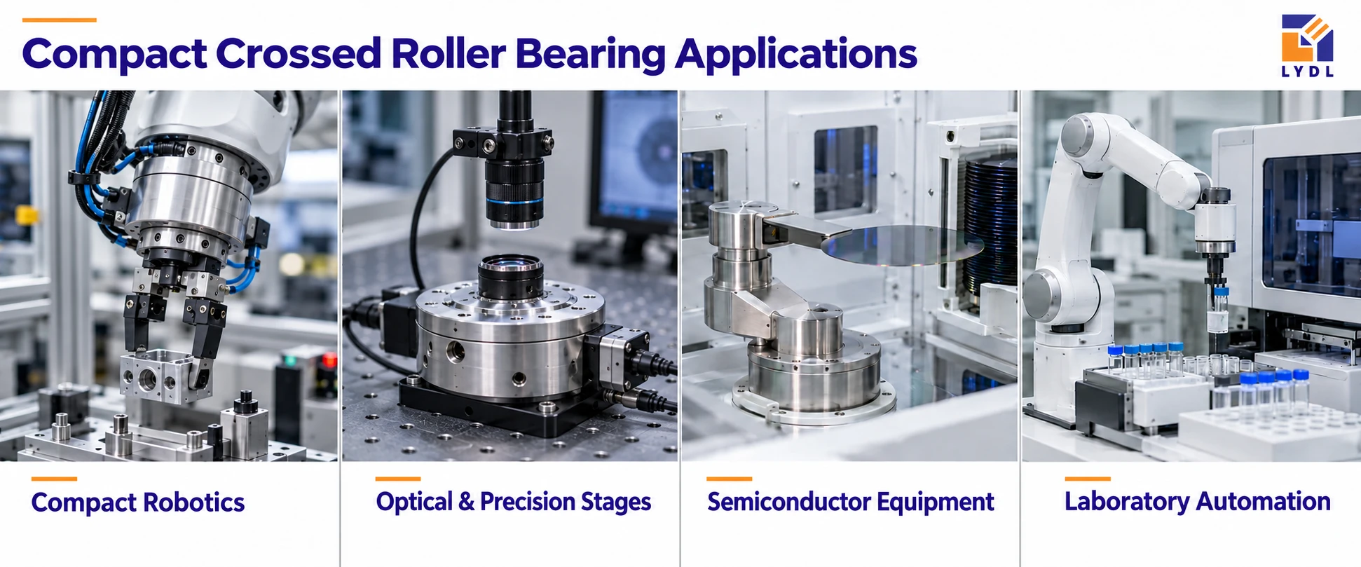
Separate the mechanical axis from the optical acceptance requirement. A bearing measured at its reference ring can meet its own runout specification while an offset optical element still moves excessively. Identify the element’s height above the bearing, its mounting diameter and the working distance. These dimensions explain how angular movement affects the useful optical position.
The RAU series size range provides neighbouring bore sizes when the optical assembly diameter changes. RAU7008 adds 10 mm of bore relative to a 60 mm model, but the retaining components and seat diameters change with it. Check the beam path, encoder cable exit and fastener access before freezing the stage diameter; a larger bore is useful only if the complete hub preserves the required passage.
An accuracy grade should be connected to a stated measurement. Record the rotating ring, the datum used for axial runout and the reference face used to position the bearing. THK’s RA-compatible suffix system distinguishes accuracy from seal and clearance choices. A precision suffix does not select a grease or demonstrate optical repeatability. Define those characteristics separately in the LYDL specification. [3]
Review the RA series comparison if a current stage uses a separable outer ring. The RAU construction may simplify handling, but the existing presser flange, alignment method and lubrication arrangement must still be examined. Do not rely on a matching nominal size to establish equivalent stage behaviour after a retrofit.
Place the encoder reference within the same structural chain as the optical element whenever the design allows. A drive-side encoder reports drive motion; it may not reveal compliance between the drive and the working stage. Document where position is measured, where accuracy is required and whether the two locations remain connected under changing load.
A thinner alternative can be found in the CRBT / RAU ultra-thin bearing range, but reducing bearing width changes the reference family and its options. Treat that comparison as a new layout study. For bidirectional positioning, list the approach directions, dwell time and allowed reversal error so the acceptance test represents actual use rather than a single unloaded sweep.
The bearing seat and retaining faces should locate the ring without forcing the surrounding stage plate into distortion. Check flatness and corner compatibility on the approved assembly drawing. Use the 0.5 mm minimum chamfer reference when reviewing mating corners, but obtain the actual corner geometry before machining a tight fit. Shoulder limits remain 73.5 mm maximum ds and 80.5 mm minimum Dh. [2, 4]
Maintain access to the four Ø1.5 mm lubrication holes. These are not sensor mounting positions and are not threaded fastening holes. Plan the lubricant route independently from encoder brackets and cable guides. When fitting the bearing, keep foreign particles away from the locating surfaces and use a seating method appropriate to the ring receiving the installation force. [2, 5]
Measure the stage before and after attaching the optical hardware. This sequence can reveal whether the bearing retention, top plate or optical mount changes the alignment. Keep the instrument position and datum consistent between checks. Record any adjustment rather than replacing a repeatable engineering measurement with a subjective judgement of smooth rotation.
Define bearing runout at the selected ring and datum. For optical-stage acceptance, add the measurement distance, approach direction and settling condition.
Protect seating faces and retain the configuration label through individual packing. Agree corrosion protection and required records. The montage explains inspection and packing methods; it does not demonstrate optical acceptance of the completed stage.

No. Optical repeatability also depends on the encoder, drive, housing, working-element mount and load condition. Specify the desired result at the optical element and its measurement method. Use bearing accuracy as one part of that system requirement, not a substitute for it.
A working element mounted above the bearing creates an offset and can amplify the effect of angular deflection. Its height and centre of gravity also affect the bearing moment. Include these dimensions with the load data instead of supplying only the element weight.
No. THK lists 77 mm as the roller pitch circle for RAU7008. It describes the internal rolling arrangement. Encoder rings and fasteners require their own controlled mounting dimensions on the stage drawing. Do not drill or design around that number as a bolt pattern. [2]
The housing shoulder Dh reference is a minimum of 80.5 mm. The shaft shoulder ds reference is a maximum of 73.5 mm. Their opposite limit directions matter when reviewing supporting faces; neither figure directly specifies shaft or housing fit clearance. [2, 4]
Include it when reversal behaviour affects the intended positioning result. State the angle, load, direction changes, dwell and measurement location. A bearing-only check and an assembled-stage reversal test should be identified separately so both parties understand the acceptance responsibility.
Provide the stage section, optical-element mounting height, encoder location and required positioning result. Include forces, moments and the reversal sequence along with quantity. To review RAU7008, contact LYDL and attach the complete reference designation. Request a drawing that identifies the bearing configuration and the inspection surfaces relevant to your optical stage.
Reference review: 10 October 2026. Brand names identify technical sources, not LYDL affiliation. The agreed LYDL drawing and quotation define supply.