

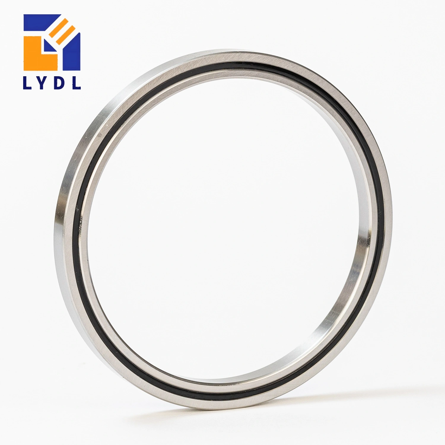
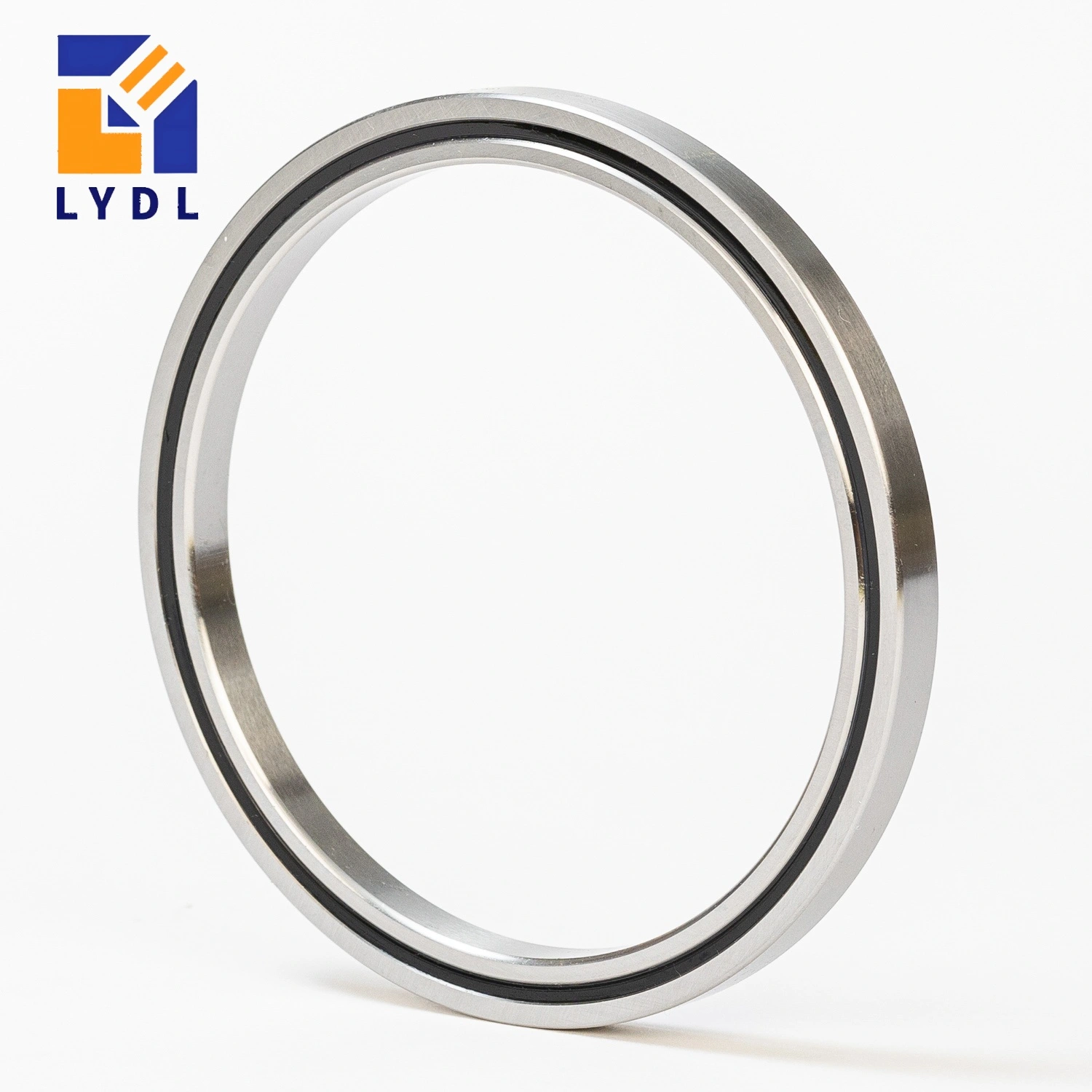
The RAU7005C0 cross roller bearing reference provides a 70 mm bore within an 81 mm outside diameter and 5 mm axial width. It is a candidate for a shallow annular axis where an encoder, sensor ring or services share limited space around the hub. The bearing’s compact dimensions do not determine the final encoder gap or assembly runout; those require a defined mounting arrangement. [3, 4]
Use the cross roller bearing selection guide to locate this open 5 mm family among the available constructions. THK’s RAU7005 row provides the verified reference data here. A 70 mm IKO CRBT counterpart was not identified in the reviewed standard catalogue, so any alternative needs its own documented ratings, configuration and mounting interface. [2, 3]
| Parameter | THK RAU7005C0 |
|---|---|
| Bore d | 70 mm |
| Outside diameter D | 81 mm |
| Width B / B1 | 5 mm |
| Radial section (D – d) / 2 | 5.5 mm |
| Roller pitch circle dp | 74.7 mm |
| Minimum chamfer r | 0.15 mm |
| Shaft shoulder ds (maximum) | 72.5 mm |
| Housing shoulder Dh (minimum) | 77 mm |
| Dynamic radial load rating C | 2.81 kN |
| Static radial load rating C0 | 4.68 kN |
| Reference mass | 44 g |
| Lubrication holes | 2 x Ø1 mm |
| Reference seals | Open; seals not supported |
| Reference clearance / accuracy | C0 / normal grade 0 |
THK gives C 2.81 kN, C0 4.68 kN and a reference mass of 44 g for RAU7005. Both catalogue ratings are radial values. They should be used with the actual force directions, moment arms and duty when evaluating an annular axis. A heavy encoder bracket or service bundle can influence the assembly through its offset and restraint even if its mass appears modest. Confirm LYDL supply data on the agreed specification. [3, 6]
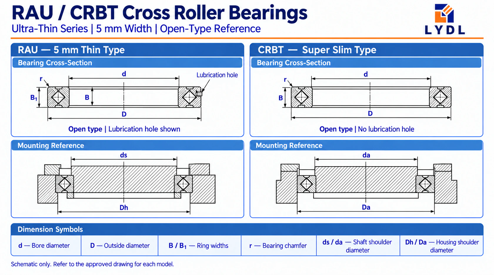
The RAU portion of the shared diagram corresponds to d = 70 mm, D = 81 mm and width B/B1 = 5 mm. Its dp is 74.7 mm, minimum chamfer r is 0.15 mm, and lubrication detail is two Ø1 mm holes. THK’s shoulder references are ds ≤ 72.5 mm and Dh ≥ 77 mm. These are support dimensions; the adjacent CRBT section is a separate construction example rather than a verified CRBT705A cross-reference. [2, 3]
An encoder ring may be referenced to a hub surface, a retaining flange or a separate carrier. Identify that datum and its relation to the bearing seating faces. The required sensing gap should be checked through the intended rotation and operating conditions. Specify whether acceptance concerns mechanical movement at the sensor or the completed feedback system.
Review the CRBT / RAU ultra-thin bearing range for the 5 mm envelope options. Include the encoder mounting land and any cable clearance in the annular support design. A gap in the support created to pass a service bundle should be evaluated as part of the load path. Nominal bore clearance alone does not describe how the supported rings will behave after retention.
THK lists C0 clearance, normal grade 0 and no seals for this small-diameter RAU family. Do not convert an encoder performance target into a standard P5 bearing claim. If a tighter LYDL runout limit is needed, state the datum, measured surface, fixture and permitted deviation. That numerical requirement can then be reviewed and agreed as part of the order. [3]
The RAU series size range includes the wider 70 × 86 × 8 mm RAU7008 reference. Moving to it changes OD, width and mounting information despite the common bore. An encoder carrier or cover built for the 81 mm seat may need redesign. Compare the complete axis, including service access, before treating the wider option as an assembly replacement.
Routing a cable through an annular hub does not eliminate cable reaction forces. Record its bending range, anchor locations and any stiffness that varies with angle. Check the completed mechanism with services installed. This allows drive-load or positioning changes caused by the bundle to be discussed using repeatable conditions rather than attributed automatically to the bearing.
The CRBH / CRBHV bearing options offers other construction choices if there is room for a larger section. Compare the existing encoder datum and service arrangement along with reference ratings. A proposed upgrade may require a new retaining flange or carrier. Preserve the target feedback performance and available envelope as separate requirements so the engineering comparison stays useful.
Confirm shoulders against ds maximum 72.5 mm and Dh minimum 77 mm. Apply the selected fit and face requirements from the approved LYDL drawing; these support references are not ready-made fit tolerances. Include corner relief around the 0.15 mm chamfer reference. The retaining arrangement should support the ring without using the encoder carrier as an unintended clamp face. [3, 5]
Identify the two Ø1 mm lubricant holes on the supplied configuration and preserve the reviewed access route. Coordinate this with the sensor enclosure and service bundle. The housing section should distinguish lubricant passages from cable openings and fixing points. A clearly annotated assembly drawing reduces the chance of confusing features during manufacture or maintenance.
Check free rotation after bearing retention, then fit the carrier and set the sensor gap. Connect the drive and services before repeating the agreed motion check. Record the same reference surfaces and angular positions. If the measurement changes, this staged sequence helps locate the influence of the added parts without relying on an unsupported precision label.
List component limits separately from encoder feedback acceptance. Record the measurement surface, holding fixture and conditions for any special ring requirement.
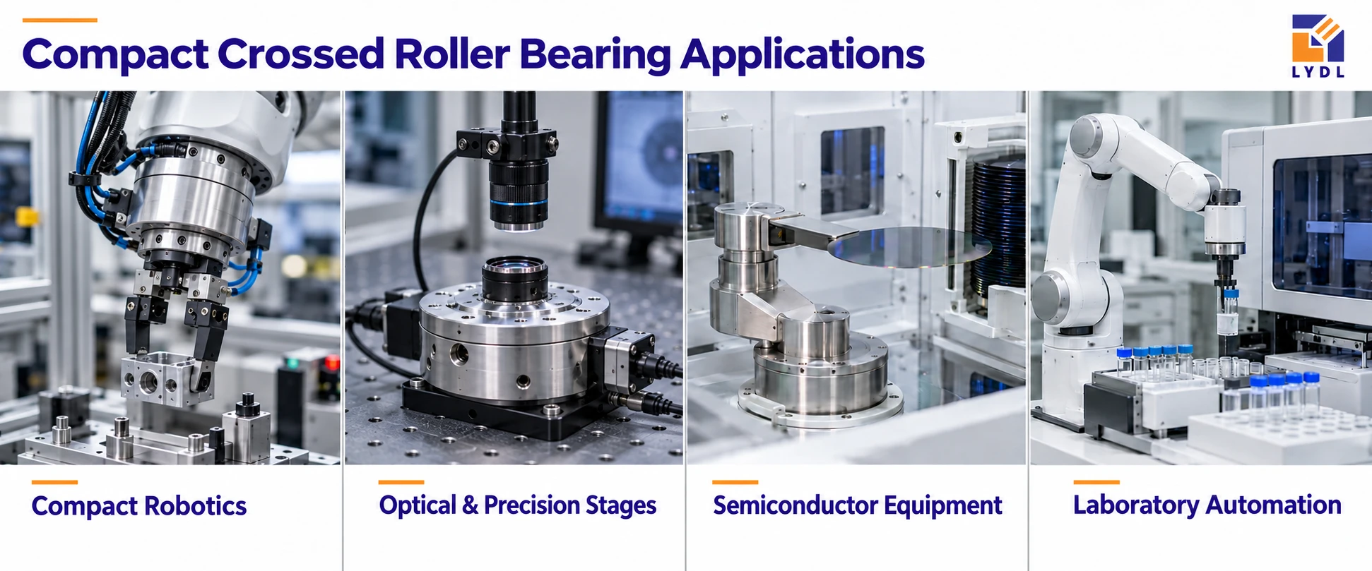
Support the thin ring in individual export protection and keep loose hardware away from locating faces. Specify labels, corrosion protection and order records. The shared montage is illustrative and does not demonstrate acceptance of the completed encoder system.

No. The bore locates a hub, while the encoder land is a feature of the surrounding assembly. Define its diameter, datum and relationship to the retained bearing. The sensor gap and complete feedback performance must be checked against that assembly definition.
It is not verified in the cited IKO standard CRBT sources. This page therefore uses the confirmed THK reference. If another supplier offers that identifier, request its drawing, accuracy limits, clearance and lubrication details before evaluating it as an alternative. [2, 3]
Establish the retained bearing and hub first, then mount the encoder carrier and set the gap using its specified datum. Repeat the relevant check after connecting the drive and services. This sequence helps expose shifts caused by later assembly steps.
Yes. A bundle can apply restraint or reaction forces that change with angle. Specify its anchors and bending range and include it in the final motion check. A hollow bore provides routing space but does not define the magnitude of those service forces.
THK lists normal grade 0 for the 5 mm RAU family, with C0 clearance and no seals. Encoder accuracy is a different assembly-level requirement. Any special LYDL ring accuracy should be agreed as numerical inspection limits rather than assigned an unsupported standard P5 suffix. [3]
Provide the encoder and hub section, sensor datum, service arrangement and motion duty. State RAU7005C0 as the reference and list bearing and assembly acceptance separately. You can contact LYDL for a LYDL drawing proposal and quotation that identifies the actual configuration, records and export protection required for this annular axis.
Reference review: 10 October 2026. Brand names identify technical sources, not LYDL affiliation. The agreed LYDL drawing and quotation define supply.