

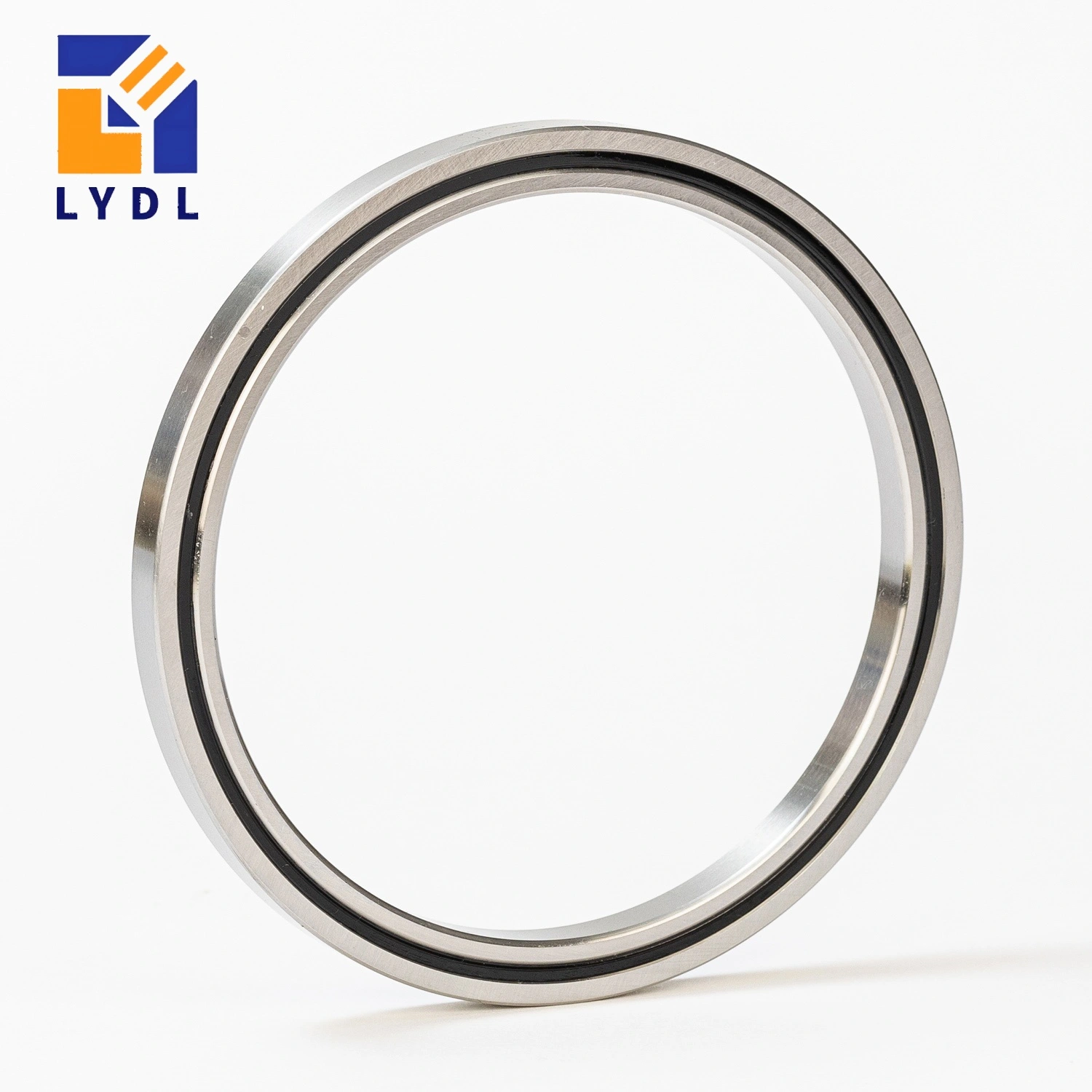
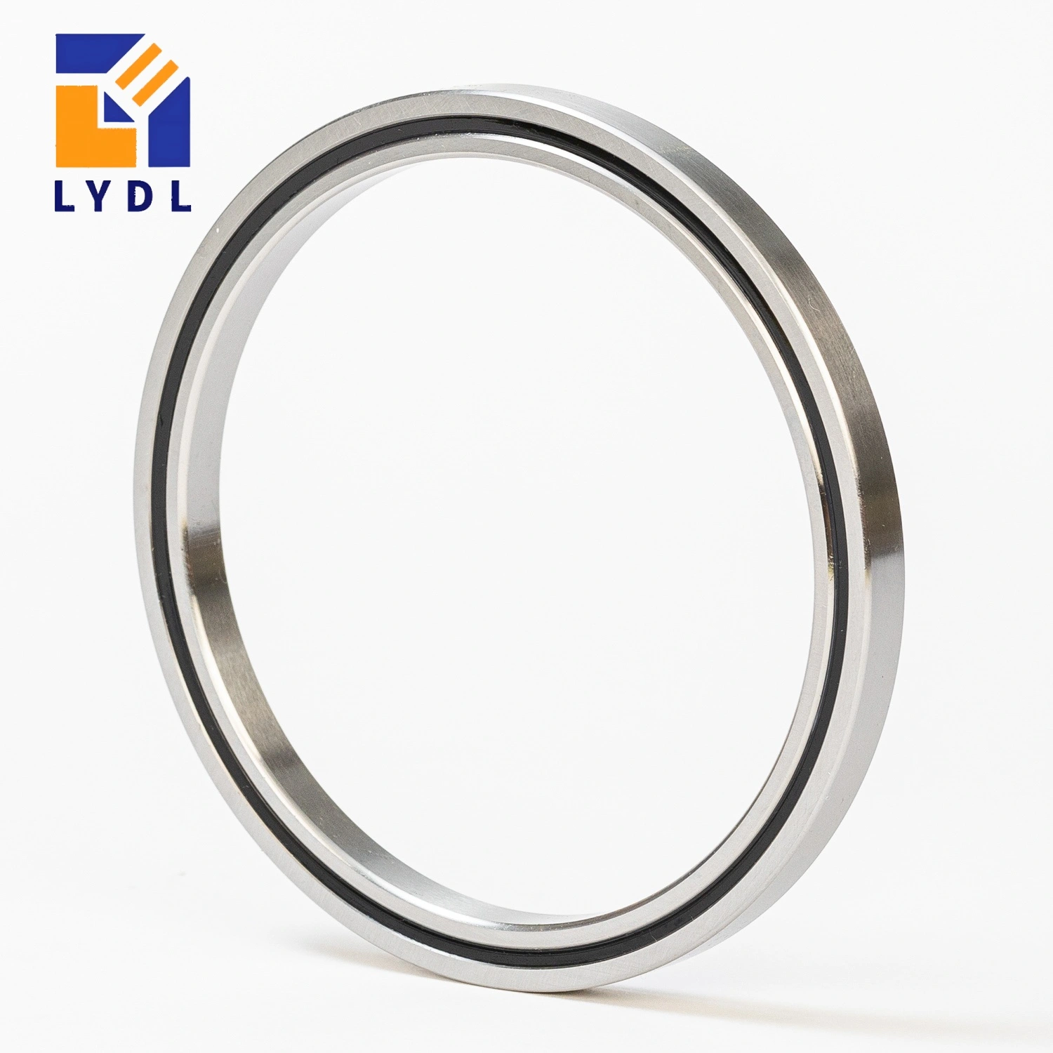
The RAU20013 cross roller bearing has a 200 × 226 × 13 mm envelope. THK’s RA-compatible reference design uses integral rings and can be evaluated for either ring rotation. Its large bore can accommodate a substantial hub, but the surrounding structure determines the useful opening and the way fixture loads are transmitted to the bearing. [1, 2]
A broad rotary fixture needs more description than diameter and total mass. Identify the fixture attachments, working load offsets and supporting frame. Begin with the cross roller bearing selection guide to select an appropriate ring arrangement, then check whether the 13 mm section can be retained and supported effectively within the complete mechanism.
| Parameter | THK RAU20013 |
|---|---|
| Bore d | 200 mm |
| Outside diameter D | 226 mm |
| Width B / B1 | 13 mm |
| Radial section (D – d) / 2 | 13 mm |
| Roller pitch circle dp | 212 mm |
| Minimum chamfer r | 0.8 mm |
| Shaft shoulder ds (maximum) | 205 mm |
| Housing shoulder Dh (minimum) | 219 mm |
| Dynamic radial load rating C | 25.80 kN |
| Static radial load rating C0 | 54.70 kN |
| Reference mass | 0.71 kg |
| Lubrication holes | 4 x Ø2 mm |
THK lists RAU20013 with a 25.80 kN dynamic radial rating, 54.70 kN static radial rating and 0.71 kg reference mass. These entries do not certify an assembled rotary table’s payload, machining duty or peripheral force capacity. Applied moments and axial forces, together with shock and required life, must be reviewed under the relevant load conditions. LYDL supplied specifications remain subject to the approved order drawing and acceptance agreement. [2, 6]
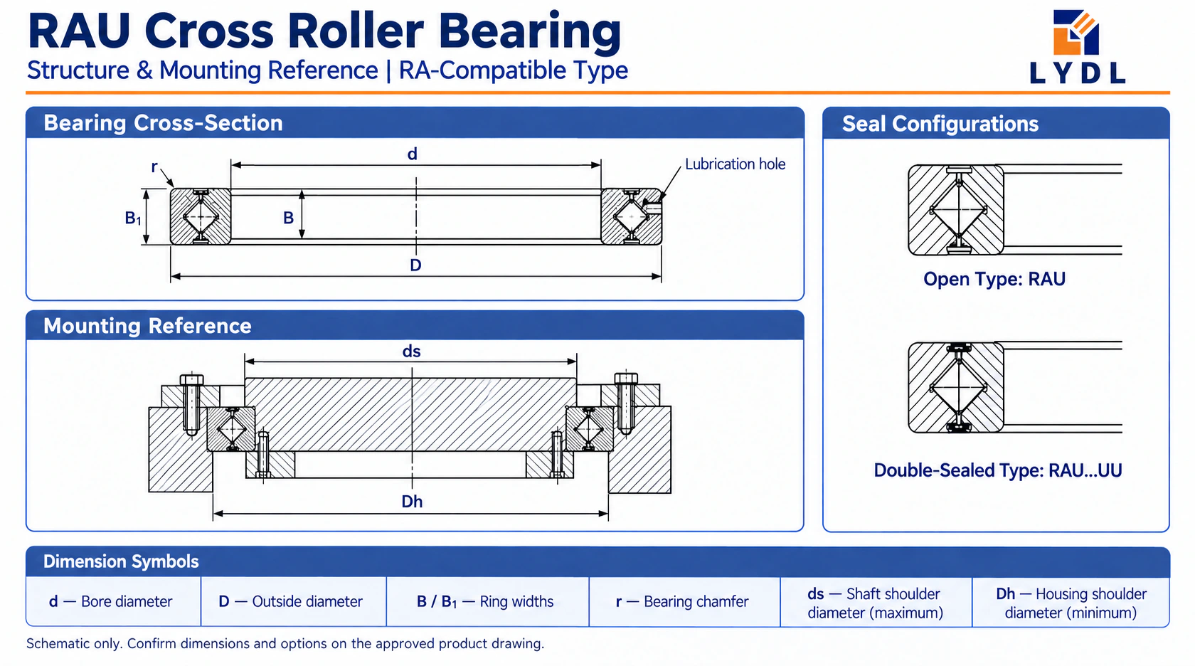
The structure diagram identifies the 200 mm bore as d, the 226 mm outside diameter as D and 13 mm widths as B/B1. Roller pitch circle dp is 212 mm. Shaft shoulder ds has a 205 mm maximum; housing shoulder Dh a 219 mm minimum. The four Ø2 mm lubrication holes and 0.8 mm minimum chamfer belong to this reference row. The graphic does not dimension a fixing pattern or internal manufacturing profile. [2]
A fixture can load the ring unevenly when its working point is distant from the bearing centre. Draw the moment directions for each important operation, including loading, positioning and any process reaction. Check that the flange and housing carry these forces through a sufficiently supported region. A local attachment lug does not guarantee circumferential ring support.
Review adjacent members of the RAU series size range if the hub or support diameter is still open. RAU20013 is a specific 13 mm-wide model, not a general designation for every 200 mm-bore rotary support. Keep its own dimensional row and mounting references in the layout. Changes to hub diameter can also affect the service route, drive position and dismantling space.
Specify the ring that rotates relative to the principal load and the face that establishes the axial position. Accuracy grade, clearance or preload and seals are separate choices in the THK reference coding. Set a measurable acceptance criterion for the relevant ring and identify any platform-level requirement independently. A large bore does not imply a particular precision class. [3]
The RA series comparison assists a same-envelope construction review if the existing unit uses a separable outer ring. Integral RAU rings alter handling and installation considerations, while seal orientation and lubrication access still require verification. Match the full original specification before approving interchangeability; dimensions alone do not establish the complete fixture’s behaviour.
Check whether the installed hub can be removed without damaging reference faces or forcing loads through the roller arrangement. A broad fixture may hide retaining hardware once assembled. Provide access to fasteners, lubricant points and the surfaces required for inspection. These provisions make the chosen bearing practical to service after the machine frame is complete.
Compare the CRBH / CRBHV bearing options when another bearing section is feasible around the work area. The comparison should include retaining parts, platform stiffness and service access, not just a radial rating. A change to a larger envelope can move the drive and fixture reference. Review those interfaces together before presenting an alternative as a straightforward replacement.
Use the 205 mm maximum ds and 219 mm minimum Dh as reference shoulder limits. Review the housing corner against the 0.8 mm minimum chamfer and actual bearing geometry. A precise bearing cannot compensate for debris, an uneven seat or a distorted retaining face. Establish the required supporting-part dimensions and fits on the approved assembly drawing before machining. [2, 4]
Maintain lubricant access to all required ports after the fixture is fitted. Four Ø2 mm openings are identified in the THK RAU20013 reference; they are not flange bolt locations. Determine their actual positions from the controlled drawing and plan the surrounding route. Review the insertion plug position relative to the most heavily loaded sector in accordance with reference assembly guidance. [2, 5]
Check rotation and runout progressively through seating, retention and fixture attachment. Use the same measurement datum when comparing results. If the fixture adds a significant offset, repeat the assembled check under a representative load. Keep drive disconnection or another suitable method available so external rubbing and coupling forces can be separated during diagnosis.
Set bearing acceptance at identified ring datums. A large fixture also needs its own test radius, payload condition and measurement method.
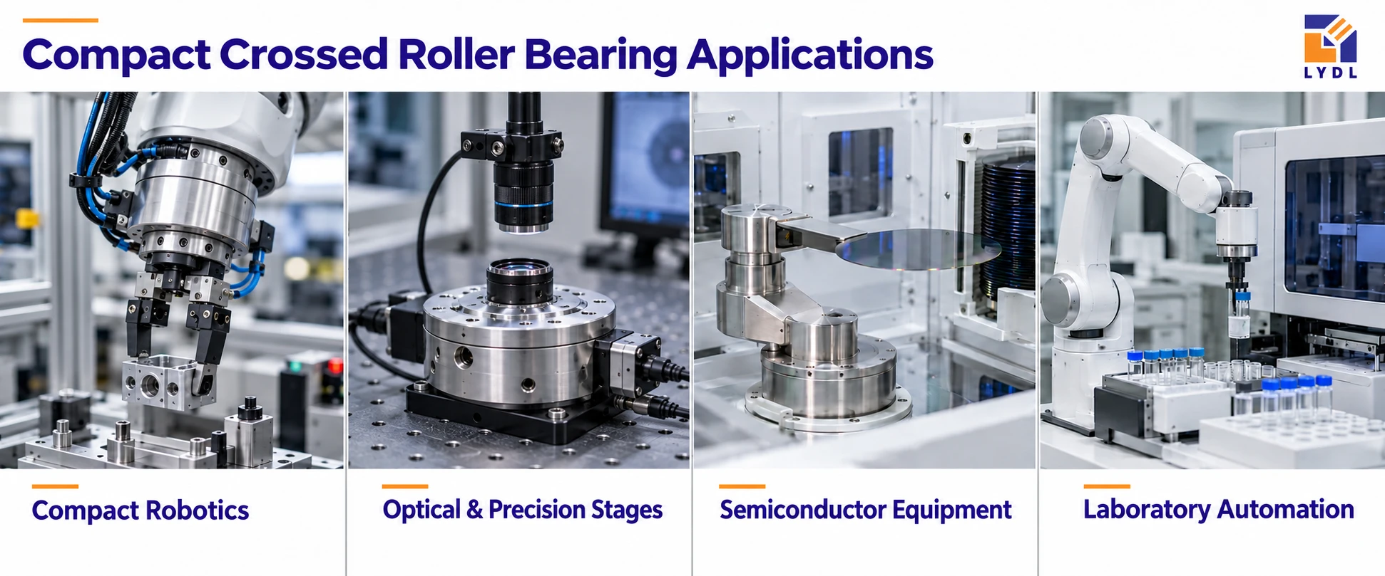
Arrange handling support for the 200 mm-bore ring and keep locating faces protected during export. Confirm individual packing, corrosion protection, labels and records. Use the montage to explain methods; shipment documents establish the actual inspection and delivery configuration.

No. It is a bearing model reference with a 200 × 226 × 13 mm envelope. The hub, platform, housing, drive and retaining components form the rotary mechanism. Their stiffness and interfaces must be assessed before assigning machine-level load or accuracy capabilities. [2]
No. The figure is the THK reference static radial rating. Fixture offset, axial force, process contact and the required safety margin must also be evaluated. Define the working load using the actual assembly and duty instead of converting the catalogue rating into a weight allowance. [2, 6]
Include wall thickness, useful central passage, locating faces, retention, service routes and the way workpiece forces enter the hub. Show removal and inspection access where relevant. The bearing bore alone does not describe those installation and maintenance requirements.
No. The RAU20013 reference identifies four lubrication holes of that diameter. They do not establish bolt sizes, thread details or a fixing circle. Design retention separately and confirm lubricant-port positions against the approved bearing and assembly drawings. [2]
Keep the two checks separate and document their relationship. Incoming measurements apply to the bearing configuration and agreed datums. Loaded-fixture measurements apply to the completed structure, load location and drive state. Record both contexts so a difference is interpreted correctly.
Send the full fixture plan and section, force locations, supporting structure and duty cycle for RAU20013. Identify seals, required ring accuracy and maintenance access. You can contact LYDL with quantity and any original replacement code. Ask for the approved model drawing, load-review scope and clearly defined inspection responsibilities with the quotation.
Reference review: 10 October 2026. Brand names identify technical sources, not LYDL affiliation. The agreed LYDL drawing and quotation define supply.