

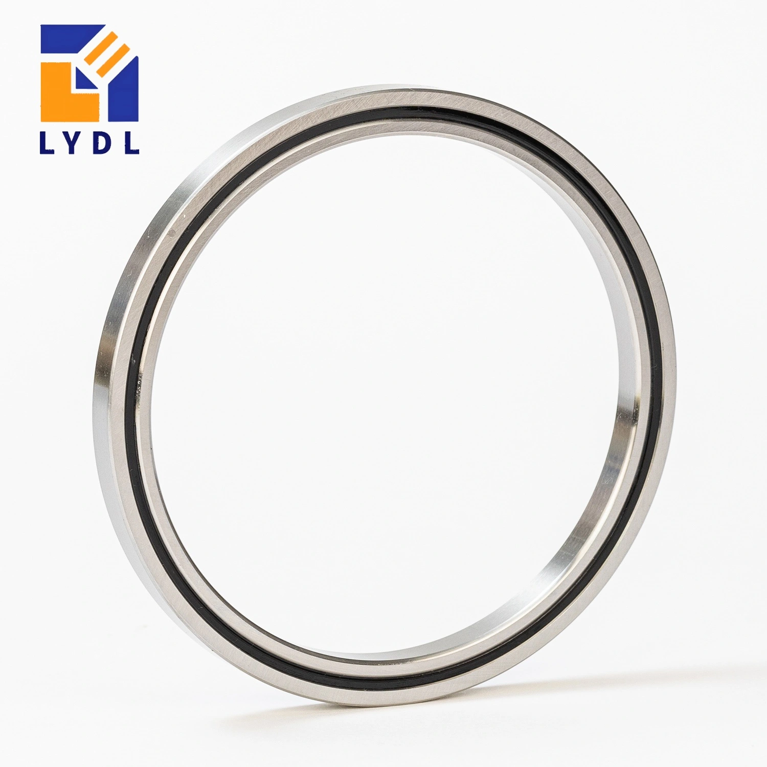
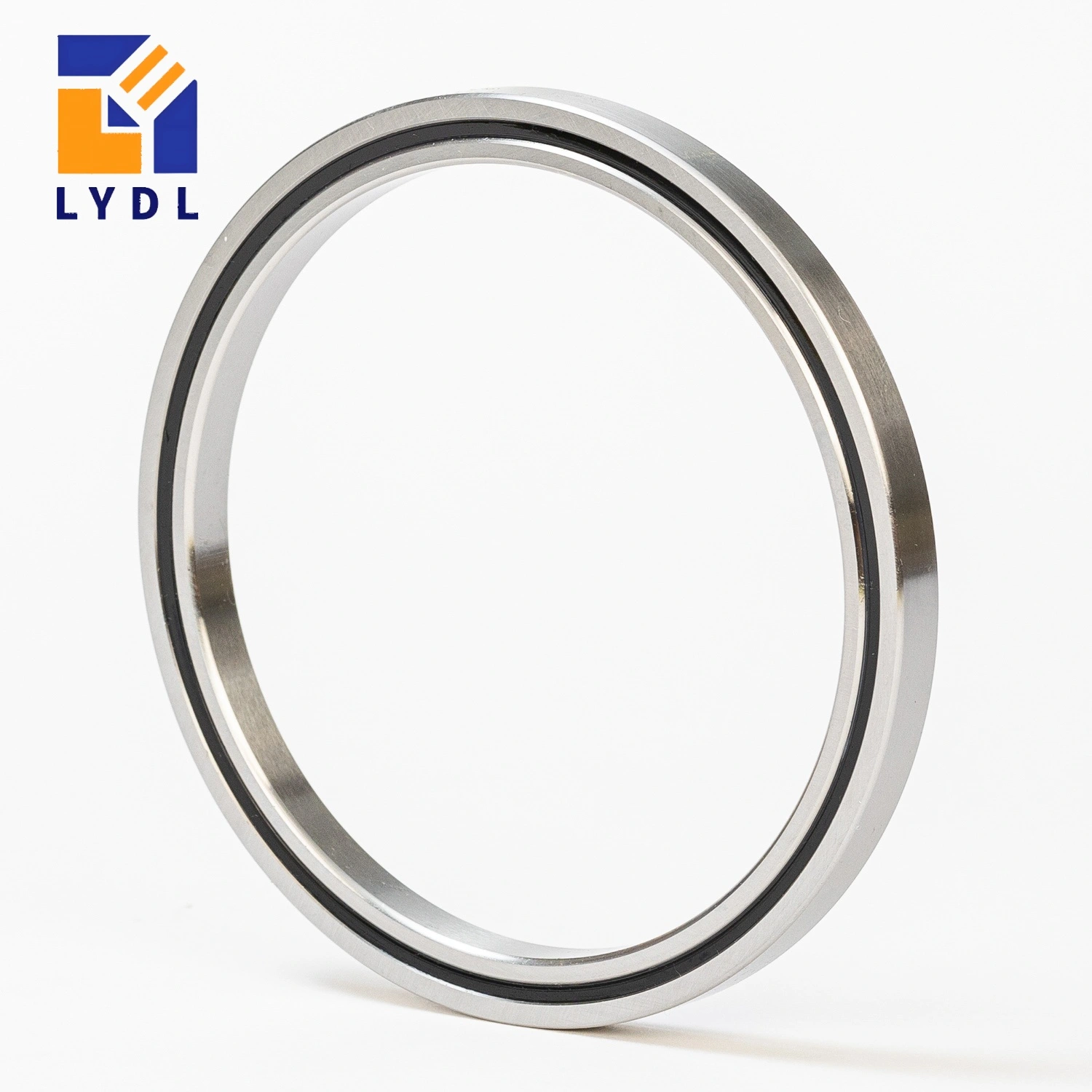
The RAU15008 cross roller bearing combines a 150 mm bore with a 166 mm outside diameter and 8 mm width. Its RA-compatible reference construction has integral inner and outer rings, suitable for examining either ring as the rotating member. The large bore is paired with a narrow section, so the surrounding support must be designed with the bearing rather than added afterwards. [1, 2]
This model can be considered for a broad but low rotary module when the available axial height is limited. The bore, retaining flange and hub still have different functions. Consult the cross roller bearing selection guide to decide whether an integral-ring arrangement matches the intended installation, and identify where the useful load enters the supported member.
| Parameter | THK RAU15008 |
|---|---|
| Bore d | 150 mm |
| Outside diameter D | 166 mm |
| Width B / B1 | 8 mm |
| Radial section (D – d) / 2 | 8 mm |
| Roller pitch circle dp | 157 mm |
| Minimum chamfer r | 0.5 mm |
| Shaft shoulder ds (maximum) | 153.5 mm |
| Housing shoulder Dh (minimum) | 160.5 mm |
| Dynamic radial load rating C | 8.82 kN |
| Static radial load rating C0 | 20.60 kN |
| Reference mass | 0.2 kg |
| Lubrication holes | 4 x Ø1.5 mm |
The THK model row lists C = 8.82 kN, C0 = 20.60 kN and a reference mass of 0.20 kg. A large diameter does not turn those radial ratings into an allowable peripheral process force or platform payload. Moment from an offset load and the required static margin must be evaluated alongside operating life. The supplied LYDL performance and configuration are established by the approved order documentation, not by the reference table alone. [2, 6]
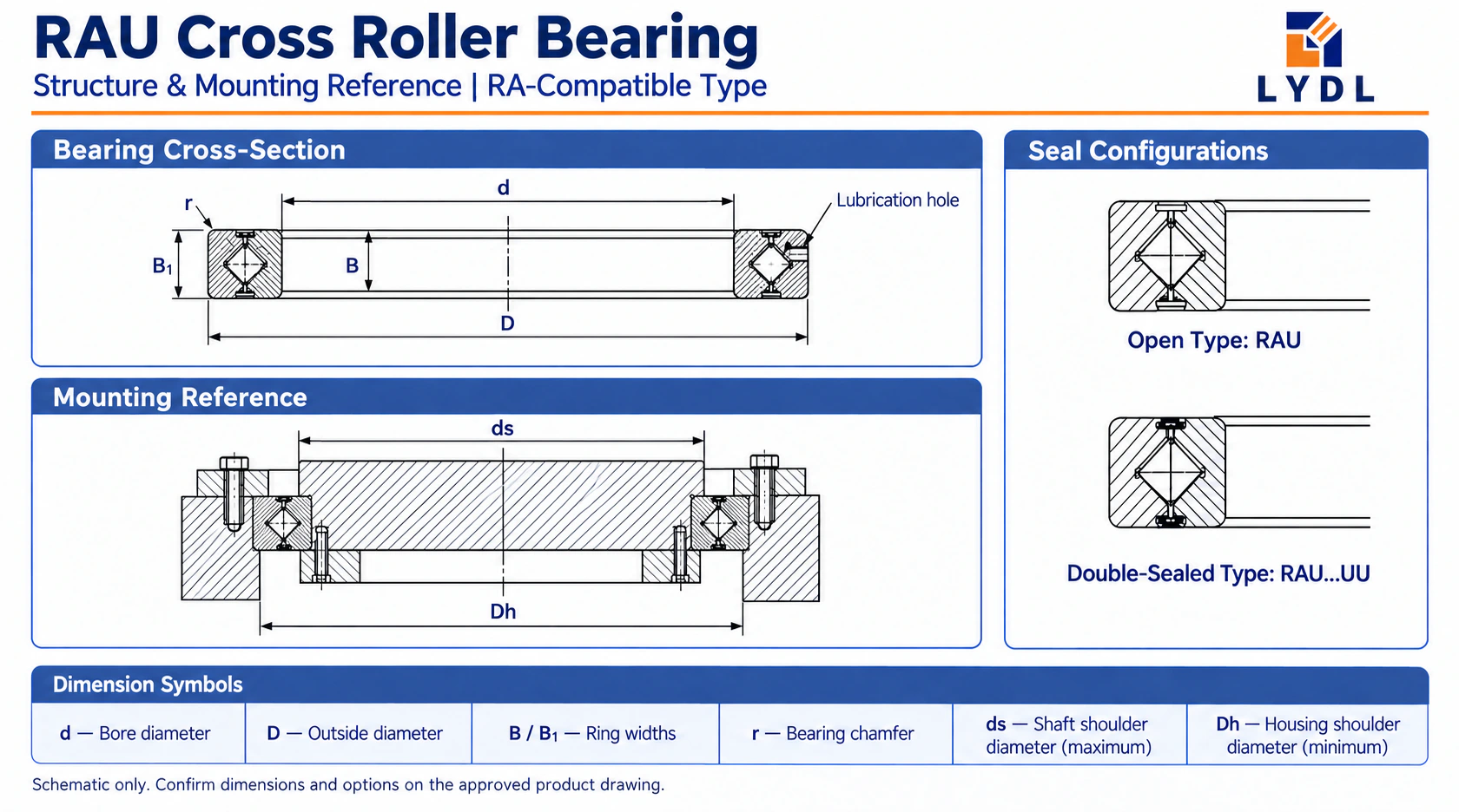
The family drawing uses d for 150 mm, D for 166 mm and B/B1 for 8 mm. Its roller pitch circle reference is 157 mm. Maximum shaft shoulder ds is 153.5 mm, and minimum housing shoulder Dh is 160.5 mm. These symbols describe mounting support around the bearing. Lubrication access is shown separately, while the open and double-sealed sections are configuration references. They do not specify the actual supplied seals or detailed raceway geometry. [2]
Start with the 8 mm radial section and the supporting annulus around it. A broad hub can transfer force through a small local area if its flange is interrupted by cut-outs or discrete pads. Review the real contact path, fastener locations and plate thickness. Full nominal contact should not be assumed where the retaining part has been extensively lightened.
Use the RAU series size range to compare bore and section changes before the hub is finalised. The transition from an 8 mm-wide model to a 13 mm-wide model is a change in assembly envelope, not a simple suffix choice. Leave room for a meaningful support arrangement and for access to inspection surfaces; the widest central opening is not always the most practical complete axis.
For a large low-profile ring, specify which reference face positions the rotating part and how runout will be measured. Seal type, clearance or preload and accuracy grade remain independent decisions in the THK reference system. If both-ring accuracy is important, identify that requirement explicitly rather than assuming that a general precision suffix covers every measurement. [3]
The RA series comparison provides a construction comparison for equipment using a split outer ring. Review the existing retention and maintenance procedure before changing to an integral RAU assembly. Record the full original bearing code, including seal orientation and clearance details where present. The shared nominal envelope is useful evidence for layout, but it is not complete replacement approval.
During fitting, support the ring and mating parts evenly. Do not let a large hub hang from an incompletely seated bearing while alignment is still being established. Define a handling fixture if the assembly makes access difficult. Installation planning can prevent local force being applied through the rolling arrangement when the intended fit is on one particular ring.
Review the CRBH / CRBHV bearing options if a different, larger section is feasible. Compare handling, support and acceptance requirements as well as radial ratings. A heavier bearing may need different retention or assembly tooling. The useful choice is the model that can be installed and supported correctly in the real mechanism, with its final geometry and operating duty reviewed together.

Check the supporting faces against ds ≤ 153.5 mm and Dh ≥ 160.5 mm, using the actual bearing drawing for all other dimensions. Verify corner clearance around the 0.5 mm minimum chamfer reference. Fits must account for the assembled materials, loading and temperature; the shoulder diameters are not a universal shaft or housing tolerance prescription. [2, 4]
Retain access to the four Ø1.5 mm lubrication holes even when the broad hub conceals the ring. They are not lifting points or flange screw positions. Show the intended lubrication route on the mechanism section. Check the insertion plug orientation relative to the most highly loaded zone and make that relationship clear in the assembly procedure where applicable. [2, 5]
Measure rotation resistance as the approved clamping sequence progresses. Check reference-face runout after seating and after the complete retained assembly is built. An observed change should be investigated at the supporting interfaces and external clearances. Keep the measurement setup consistent so the record can distinguish a mounting effect from a different instrument position.
Define inspection of the ring datums separately from the broad hub’s runout. State the support fixture and numerical acceptance where required.
Protect the narrow ring during handling and export without transmitting package pressure through unsupported areas. Agree model labels, corrosion protection and records. The shared montage illustrates methods, while actual reports establish what was checked for the order.

It is an 8 mm-wide reference with a 150 × 166 × 8 mm envelope. RAU16013 belongs to a larger-section part of the range and measures 160 × 186 × 13 mm. Do not infer width solely from the large bore. [2]
No. Bore size does not establish the stiffness of the flange, hub or housing. Review the support annulus, plate cut-outs and applied load locations. A bearing selected from catalogue ratings still needs a sufficiently rigid and correctly contacting retention arrangement.
No. The four Ø1.5 mm openings are lubrication holes in the reference design, not lifting or fixing points. Use an assembly fixture appropriate to the ring and mating part. Do not attach handling hardware to features that are not designed and approved for it. [2]
Use a method that supports the hub and applies installation force to the ring receiving the fit. Avoid leaving the hub’s weight on a partly seated assembly. The installation procedure and fixture should be reviewed with the actual shaft and housing geometry.
Specify the measurement radius, datum, load pattern and operating state of the assembled platform. Keep that requirement separate from bearing-ring runout. The point where movement matters can be far from the reference ring surface, so an unexplained accuracy figure is insufficient.
Send the broad-hub section, support annulus, fixture positions and installation sequence for RAU15008. Include load offsets, operating conditions and required inspection datums. You can contact LYDL with quantity and the full replacement specification. Confirm the agreed bearing configuration, handling requirements and model-specific acceptance drawing before ordering.
Reference review: 10 October 2026. Brand names identify technical sources, not LYDL affiliation. The agreed LYDL drawing and quotation define supply.