


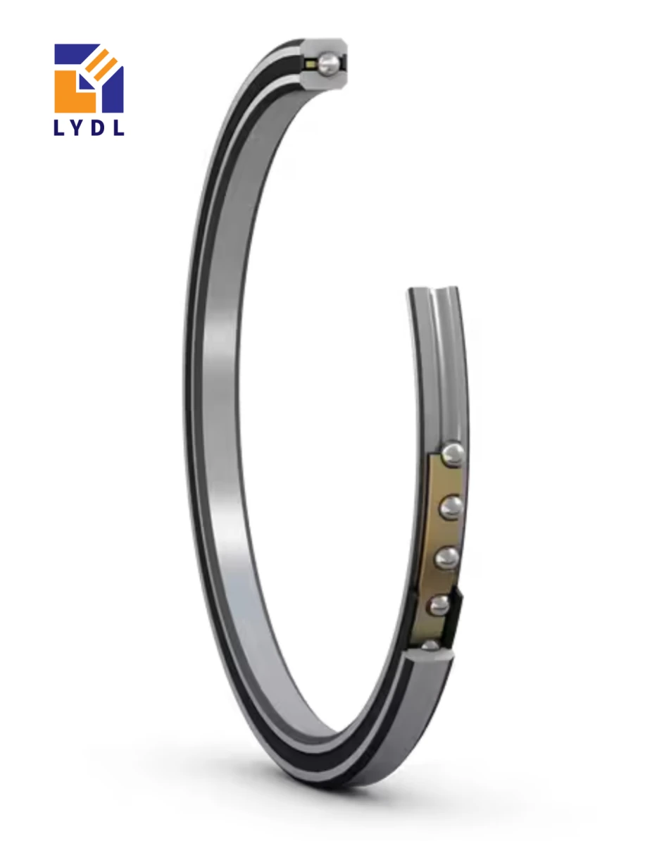

K10008CP0 / J10008CP0 reference the 100 mm bore, 116 mm outside diameter and 8 mm width of LYDL PC10008 / PC10008UU. These radial contact bearings are offered as open and double-sealed configurations. For a two-support shaft, their selection should start with a clear axial locating strategy. If both supports unintentionally lock the shaft, assembly tolerances or thermal movement can introduce loads that were absent from the original radial-load calculation.
| Specification | LYDL PC10008 | LYDL PC10008UU |
|---|---|---|
| Closure | Open | Double sealed |
| Contact geometry | Radial contact, Type C | Radial contact, Type C |
| Bore / outside diameter | 100 / 116 mm | 100 / 116 mm |
| Width / radial section | 8 / 8 mm | 8 / 8 mm |
| Approximate catalog mass | 0.14 kg | 0.14 kg |
| KAYDON reference | K10008CP0 | J10008CP0 |
The available closure designations are listed in the LYDL metric radial-contact series.
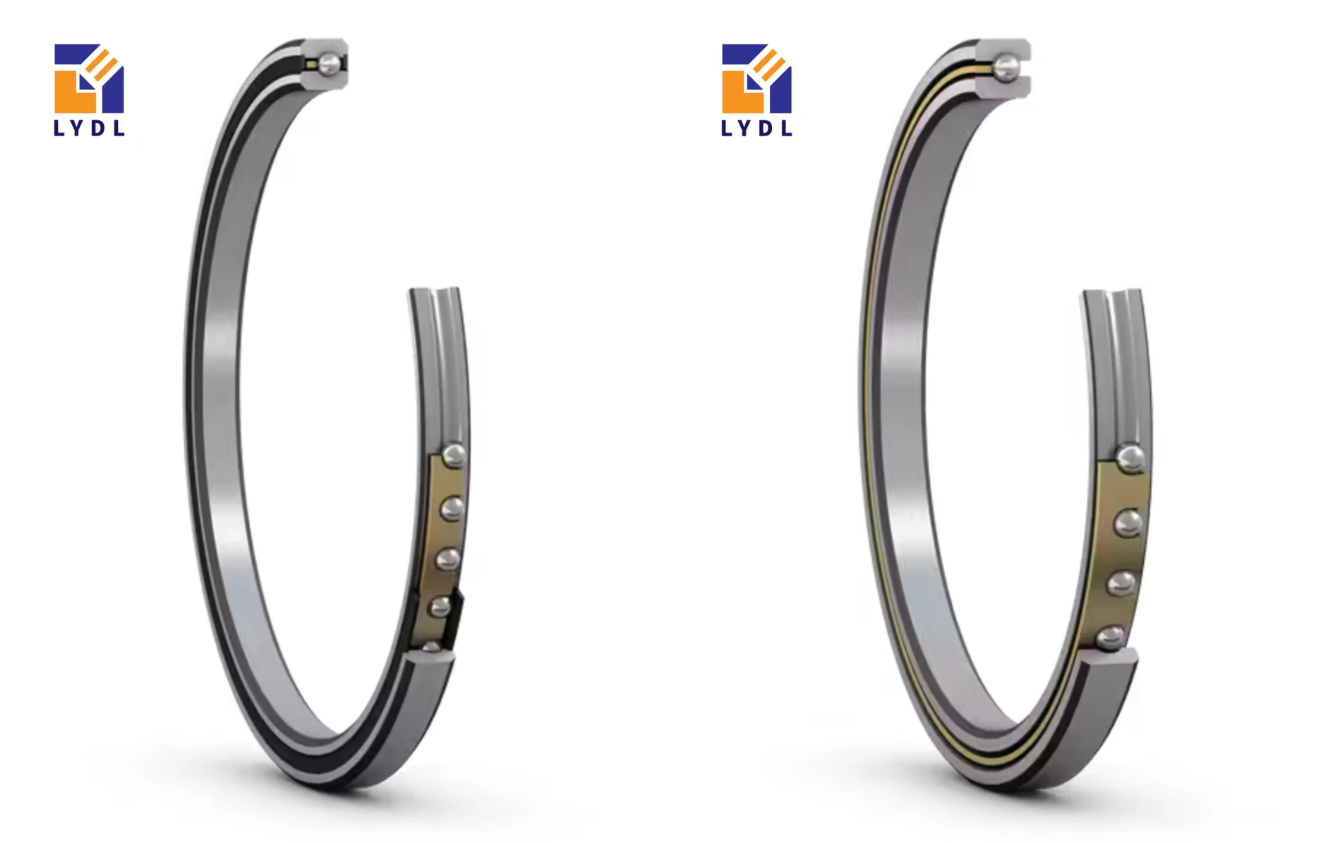
Draw the shaft and housing as an axial stack, marking every shoulder, spacer, cover and retaining element. Identify the support responsible for locating the shaft. Then show how the remaining support accommodates the displacement expected from tolerances and operating conditions. The solution must be intentional and compatible with the ring loading and required fits.
A radial ball bearing is not automatically a non-locating support simply because it is described as Type C. In some arrangements displacement occurs between a bearing ring and its seat; other arrangements use a different bearing concept. Confirm the chosen mechanism rather than relying on unintended looseness.
The 8 mm bearing width describes the boundary envelope, not the amount of axial movement available in the assembled system. Do not use internal clearance as an undefined allowance for shaft expansion. Review axial loading as well as radial reactions, particularly when collars or covers are adjusted during installation.
Discuss the PC10008 drawing and operating conditions.
KAYDON reference data — K10008CP0 / J10008CP0. These published figures are not LYDL test results or a certified LYDL load rating.
| Radial rating basis | Reference value |
|---|---|
| Dynamic, KAYDON method | 4,972 N |
| Dynamic, ISO method | 8,034 N |
| Static | 10,405 N |
The catalog identifies ISO 281:1990 as the ISO calculation basis, for comparison only. Keep the two dynamic ratings separate. Dynamic values use one million revolutions of L10 life; static values assume rigid shaft and housing support. The LYDL table labels force capacities in kg, so those entries have not been relabeled as N.
For J10008CP0, the catalog lists 1700 rpm at loads up to 20% of dynamic capacity and 0.15 N·m maximum no-load torque, with standard internal fit and lubricant at room temperature and under 5 lbf thrust. Neither number establishes the permissible duty of the supplied LYDL configuration. No-load torque is frictional resistance, not moment capacity.
A machine builder may place PC10008 bearings at two stations to support a hollow drive shaft. The pulley or coupling loads establish radial reactions, while the functional component determines where axial position must be controlled. Put the locating function close enough to that component to meet the machine's positioning requirement, subject to a complete design review.
PC10008UU can be evaluated where local seals are desirable. PC10008 may suit a common lubricated enclosure. Neither variant establishes the overall shaft arrangement by itself; the shoulders, fits and displacement path remain part of the machine design.

Measure the relevant shoulder spacing and spacer lengths against the drawing. Keep bearing tolerances and mating-component tolerances in the same axial stack calculation. A cover that appears to close correctly can still force an unintended axial load through the bearings.
Use the specified sequence for locating the shaft and securing the opposite support. Verify the intended displacement function under representative assembly conditions, including the final fastener tightening state. A dry bench check with covers loose is insufficient if the final enclosure changes the constraints.
If resistance rises after fitting a spacer or cover, stop and check the stack and ring contact surfaces. Do not compensate by omitting a required spacer or reducing fastener torque without engineering approval. Record the measured condition so that corrective action addresses the source of the constraint.
The LYDL purchase choices are PC10008 — open and PC10008UU — double sealed, cross-referenced to K10008CP0 / J10008CP0. A common product page should still record each configuration separately on the quotation, drawing and packing identification.
In KAYDON's metric code, C means radial contact, P identifies the standard formed snap-over separator, and 0 denotes class 1 / ABEC 1F. K is the open steel series; J identifies steel bearings with two nitrile seals. These suffixes do not certify LYDL material, accuracy or clearance.
NBC denotes NSK's radial thin-section family, whereas NBX denotes four-point contact. That distinction helps identify the bearing concept, but it does not establish an exact NBC substitute for this 100 mm metric seat or an equivalent axial locating arrangement.
For sample approval, document the axial datum, the location where displacement is checked and the final clamping condition. Confirm rotation and any agreed shaft end-position requirement. If the bearing is approved as part of a matched assembly process, preserve that process in production instructions rather than recording only the component number. Request material, clearance and lubrication details needed to complete the stack review.

Some engineered arrangements deliberately control both supports, but unintended double location can create unwanted axial loading. The correct answer depends on the stack tolerances, temperature changes and required internal condition. Provide the full assembly drawing instead of specifying two independently clamped bearings without an axial analysis.
No such feature is established by the UU designation. Here UU identifies double seals. Any required displacement must be provided by an approved mounting arrangement or another suitable bearing concept. Seal choice and axial location should be treated as separate design decisions.
Not automatically. Fit selection must also account for load direction, ring creep, support and accuracy. Introducing clearance without reviewing those factors can create another problem. First identify where the stack is constrained and select a deliberate displacement strategy with the bearing supplier and machine designer.
The cover may change the axial stack, contact the wrong surface or distort a seat. Compare the measured shoulder and spacer dimensions with the drawing, and inspect contact marks. Test at the specified tightening condition; a free-running result with a loose cover does not validate the final arrangement.
A different section changes the envelope and radial reference ratings, but it does not resolve an undefined locating scheme. Establish the required axial function and load first. If PC10013 is considered, redesign the housing and stack for its 126 mm outside diameter and 13 mm width.
Compare a thicker section at the same bore or a larger 8 mm-section seat when the complete arrangement changes:
K10013CP0 — 100 × 126 × 13 mm · K12008CP0 / J12008CP0 — 120 × 136 × 8 mm
Send both bearing-station drawings, shoulder spacing, spacer tolerances and the required shaft axial position. Include radial and axial loads, operating temperatures and the preferred closure. A configuration-specific quotation can then address the actual support arrangement instead of only the bearing dimensions.
Send your PC10008 selection details to LYDL.