

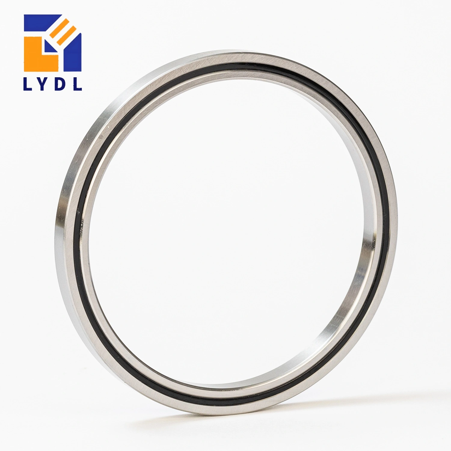
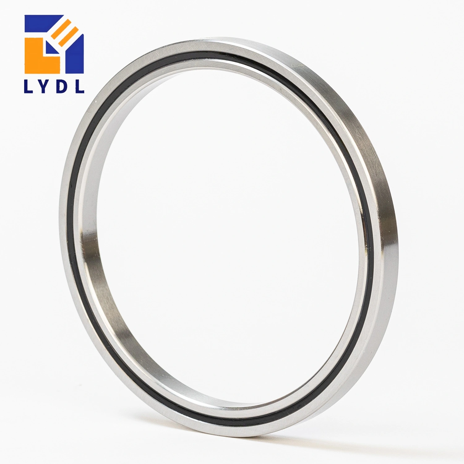
The CRBT405A cross roller bearing reference has a 40 × 51 × 5 mm envelope. THK RAU4005C0 matches that nominal size but retains its own load data and structural details. A narrow cartridge may benefit from the 5 mm axial width, provided the housing and flange preserve adequate support and service access. Both catalogue references are open types. [1, 3]
A cartridge is useful when its bearing seat, drive attachment and protection can be treated as one assembly. Before selecting the size, review the retaining path and the actual rotating ring. The cross roller bearing selection guide provides the family comparison; the cartridge section should then show where force enters and how each ring is supported.
| Parameter | IKO CRBT405A | THK RAU4005C0 |
|---|---|---|
| Bore d | 40 mm | 40 mm |
| Outside diameter D | 51 mm | 51 mm |
| Width (IKO B / THK B, B1) | 5 mm | 5 mm |
| Radial section (D – d) / 2 | 5.5 mm | 5.5 mm |
| Roller pitch circle dp | Not stated in cited IKO row | 44.7 mm |
| Minimum chamfer r | 0.15 mm | 0.15 mm |
| Shoulder (IKO da / THK ds max) | 42.5 mm | 42.5 mm |
| Shoulder (IKO Da / THK Dh min) | 47 mm | 47 mm |
| Dynamic radial load rating C | 2.00 kN | 2.14 kN |
| Static radial load rating C0 | 2.520 kN | 2.74 kN |
| Reference mass | 26.5 g | 27 g |
| Lubrication holes | None in standard CRBT…A | 2 x Ø1 mm |
| Reference seals | Open type | Open; seals not supported |
| Reference clearance / accuracy | C1 / normal grade 0 | C0 / normal grade 0 |
IKO publishes C 2.00 kN and C0 2.520 kN for CRBT405A. THK gives 2.14 kN and 2.74 kN for RAU4005. Reference masses are 26.5 g and 27 g. These are separately sourced radial ratings, not interchangeable labels for one test result. A housing cartridge must be checked for its own forces, moment offsets and required life, with actual LYDL supply requirements defined on the agreed drawing. [1, 3, 6]
The shared diagram describes d = 40 mm, D = 51 mm and 5 mm width. THK’s roller pitch circle is 44.7 mm. Its ds support limit is a maximum of 42.5 mm and Dh a minimum of 47 mm; IKO shows da/Da mounting dimensions. Standard CRBT405A has no oil hole, while RAU4005 has two Ø1 mm lubrication holes. Choose the appropriate panel instead of merging these features into an invented common structure. [1, 3]
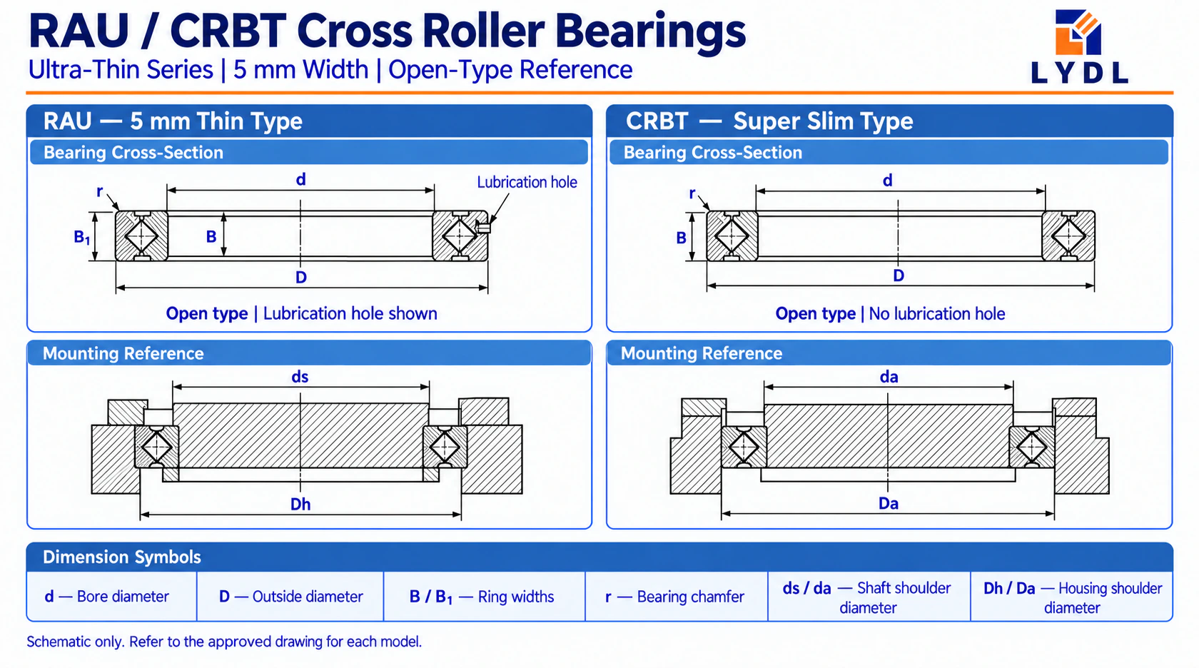
The 5 mm bearing width does not equal the finished cartridge height. A retaining flange, protective cover and drive connection add axial space. Draw their contact faces and make the tolerance relationships visible. A cartridge that is compact in an exploded view can become over-constrained if several parts attempt to locate the same ring independently.
Use the CRBT / RAU ultra-thin bearing range when comparing bore sizes around the cartridge hub. Keep the support annulus continuous enough for the actual load direction, and include access openings in the review. Fixing a narrow ring into a housing through a few unintended contact points can change assembly behaviour even when all nominal diameters appear to match.
The official references retain open construction and normal-grade accuracy. IKO uses C1 clearance for standard CRBT…A, while THK specifies C0 for its 5 mm RAU. Their catalogues do not support a standard P5 assertion for this pair. A custom LYDL requirement needs explicit runout and dimensional limits, datum surfaces and agreement before it becomes a supply specification. [2, 3]
Review the RAU series size range if the application can use the wider RA-compatible family. Its optional seals and accuracy coding apply to a different reference group. If replacing a cartridge component, identify its lubricant interface and full original designation along with the envelope. These details determine whether the proposed item matches the retained assembly.
An external cover can protect an open bearing without becoming part of the bearing’s own catalogue seal configuration. Describe the cover clearance and expected contaminants. If liquids can reach the cartridge, specify the route and required protection rather than calling the standard open reference waterproof. Protection should remain compatible with the chosen maintenance method.
Compare the CRBH / CRBHV bearing options if cartridge diameter or height may increase. Recheck retention and covers; an alternative envelope requires an updated cartridge layout.

Inspect the shoulder and flange geometry using the selected reference’s mounting symbols. The THK ds/Dh limits are support dimensions, not ready-made shaft fits. Check corner relief around the 0.15 mm minimum chamfer reference and agree the actual bearing seat tolerances. Define which surface establishes axial location so the retained ring is not forced between inconsistent references. [1, 3, 5]
Preserve the proper lubricant arrangement: RAU4005 shows two Ø1 mm holes, standard CRBT405A none. The housing drawing should identify its selected design clearly. If a cover encloses the outside ring, review access after installation. Do not add a feed hole or sealing feature to the bearing by interpreting the illustrative graphic as a manufacturing drawing.
Build the cartridge in defined stages and check rotation after each relevant retention step. Fit covers with their approved clearance, then connect the drive. A recorded sequence helps separate flange-induced resistance from cover rubbing or drive misalignment. Use consistent datums for any runout comparisons, especially after changing the external cartridge parts.
Distinguish bare-bearing inspection from cartridge acceptance. Identify the selected design, fixture and datum for each agreed numerical limit.
Protect cartridge locating faces and separate open bearings from loose hardware. Agree labels, corrosion protection and records. The montage illustrates methods; documents should identify whether inspection covered a bare bearing or an assembled cartridge.

No. Flanges, covers, drive connections and their clearances also occupy space. Define the complete axial stack and locating surfaces. Bearing width describes the component, while finished cartridge height and alignment depend on the full retained assembly.
No. Standard CRBT405A remains an open reference. A cover is a separate assembly protection feature and needs its own clearance and contamination review. Describe it as part of the cartridge rather than assigning an unsupported bearing seal suffix or environmental rating. [1, 2]
THK publishes 2.74 kN for RAU4005. IKO publishes 2.520 kN for CRBT405A. The nominal dimensions are shared, but the rating columns remain separate. Confirm the intended design and the approved LYDL values before using either figure as supplied-product data. [1, 3]
If multiple cartridge parts impose inconsistent axial positions, retention can distort the assembly or change rotation resistance. Define the locating face and the intended clamp contact. A clear reference scheme makes dimensional inspection and assembly diagnosis more reliable.
Only if the actual supplied configuration and housing interface have been approved to do so. The standard references differ: RAU4005 has two Ø1 mm lubrication holes; CRBT405A has none. Preserve that distinction during the comparison instead of assuming a common feed arrangement. [1, 3]
Provide the cartridge section with locating faces, covers, drive interface and maintenance route. Identify CRBT405A or RAU4005C0 as the intended reference and state any special limits numerically. You can contact LYDL with quantity and exposure conditions to obtain a configuration proposal tied to the actual cartridge acceptance requirements.
Reference review: 10 October 2026. Brand names identify technical sources, not LYDL affiliation. The agreed LYDL drawing and quotation define supply.