

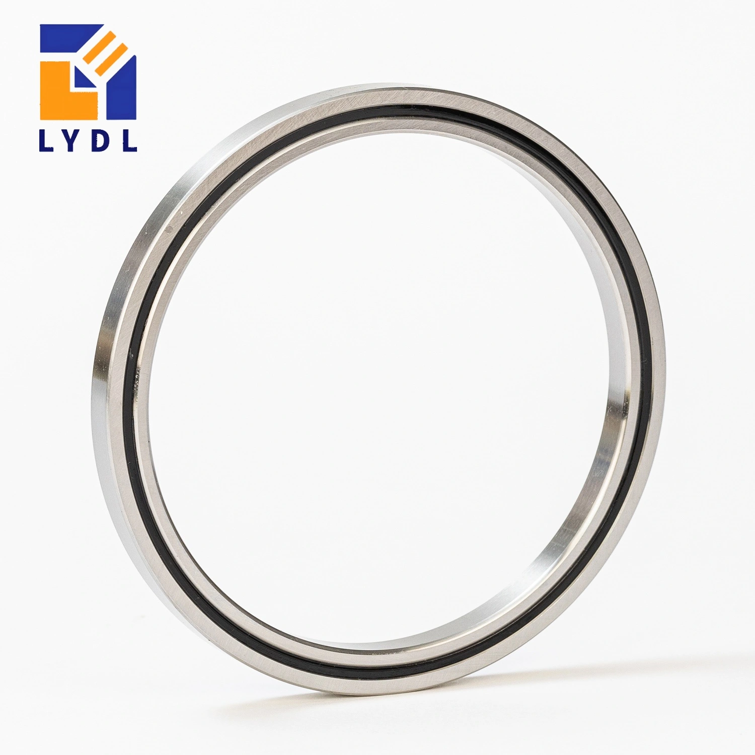
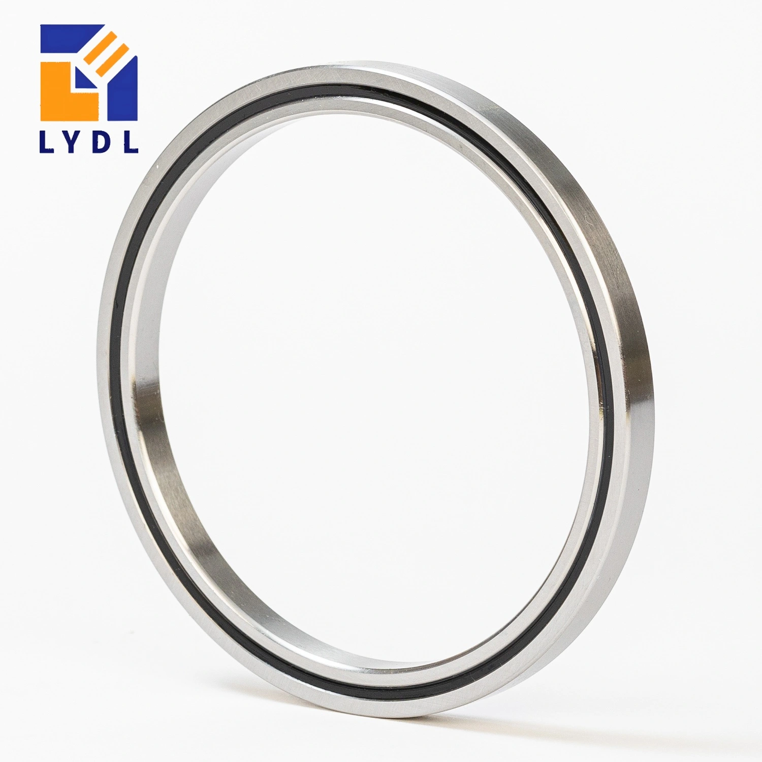
The CRBT305A cross roller bearing reference measures 30 × 41 × 5 mm. THK RAU3005C0 occupies the same nominal envelope but has a different reference specification. The slim dimensions can be evaluated for an optical mount or a compact rotary instrument. This page separates the source data so a comparison does not turn two different references into one unqualified performance claim. [1, 3]
The useful optical result depends on the bearing, working-element mount and position-feedback arrangement together. Identify the element’s offset and measurement location before choosing a precision description. Use the cross roller bearing selection guide to select the rotary bearing construction, then state the accuracy needed at the instrument rather than only at its shaft seat.
| Parameter | IKO CRBT305A | THK RAU3005C0 |
|---|---|---|
| Bore d | 30 mm | 30 mm |
| Outside diameter D | 41 mm | 41 mm |
| Width (IKO B / THK B, B1) | 5 mm | 5 mm |
| Radial section (D – d) / 2 | 5.5 mm | 5.5 mm |
| Roller pitch circle dp | Not stated in cited IKO row | 34.7 mm |
| Minimum chamfer r | 0.15 mm | 0.15 mm |
| Shoulder (IKO da / THK ds max) | 32.5 mm | 32.5 mm |
| Shoulder (IKO Da / THK Dh min) | 37 mm | 37 mm |
| Dynamic radial load rating C | 1.77 kN | 1.89 kN |
| Static radial load rating C0 | 1.970 kN | 2.14 kN |
| Reference mass | 20.7 g | 21 g |
| Lubrication holes | None in standard CRBT…A | 2 x Ø1 mm |
| Reference seals | Open type | Open; seals not supported |
| Reference clearance / accuracy | C1 / normal grade 0 | C0 / normal grade 0 |
The IKO column gives C 1.77 kN and C0 1.970 kN for CRBT305A, with 20.7 g reference mass. THK gives C 1.89 kN, C0 2.14 kN and 21 g for RAU3005. These ratings belong to their respective designs. They cannot directly establish optical-mount payload or allowable tilt; load offsets and the complete support need evaluation before specifying the supplied LYDL item. [1, 3, 6]
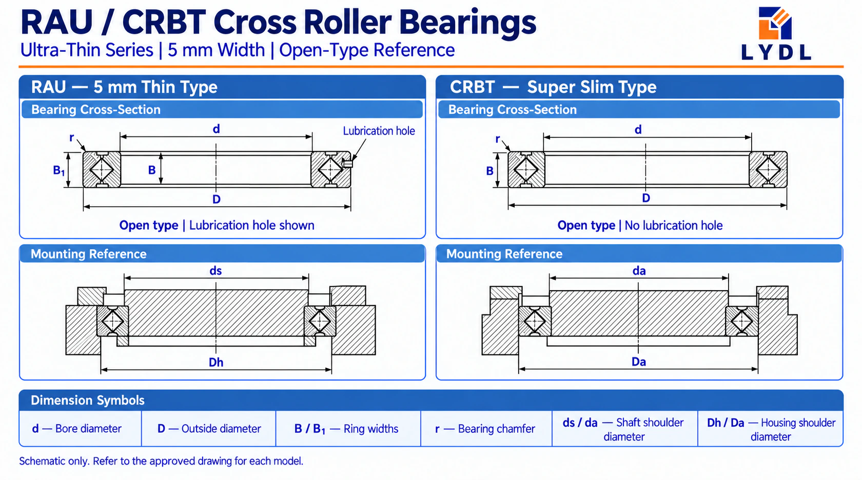
Read d as 30 mm, D as 41 mm and width as 5 mm. The radial section is 5.5 mm, while THK’s roller pitch circle is 34.7 mm. Its shoulders are ds maximum 32.5 mm and Dh minimum 37 mm. IKO uses da/Da for mounting references. The RAU drawing includes two Ø1 mm lubricant openings, and the standard CRBT drawing has none. Those differences should remain visible in the assembly review. [1, 3]
Name the surface that establishes optical alignment and the distance from that surface to the bearing. An instrument bracket can introduce angular movement even when the bearing-ring runout is within its own requirement. Document mounting height, element mass and attachment points so the reviewer can understand where the optical error is observed.
Compare the CRBT / RAU ultra-thin bearing range when choosing the shaft diameter around a beam or service path. The 30 mm bearing bore is a seat dimension, not automatically a clear optical aperture. A hub wall, fasteners or a protective tube can occupy that space. Show the finished passage and element sweep separately, including clearance at the extreme adjustment angles.
The cited IKO CRBT…A standard offers normal-grade accuracy and C1 clearance. THK’s 5 mm RAU reference uses C0 and normal grade 0, without seals. Neither standard listing establishes the P5 suffixes in the original candidate table. Any tighter LYDL accuracy request should be written as numerical limits with a defined datum and method, then approved independently. [2, 3]
Consult the RAU series size range for wider RA-compatible options when a different axial section is practical. Their configuration range is distinct. For an optical-stage retrofit, keep the original full code and acceptance method available; matching 30 × 41 × 5 mm alone does not resolve lubricant features, clearance or the resulting pointing performance.
An optical position is often used after the axis has stopped. State the permitted settling time and whether the target must be reached from both directions. Drive behaviour, cable drag and structural compliance can affect the result. Describe the test at the optical element so a component-level bearing inspection is not confused with complete instrument acceptance.
The CRBH / CRBHV bearing options provides other construction options if a larger section fits. Preserve the optical datum, clear aperture and pointing test in that comparison.

Inspect the shaft and housing seating surfaces before fitting. Verify the corner relationship around the 0.15 mm minimum chamfer reference, and use the approved design to establish fits. The support dimensions do not provide a bolt pattern or a complete tolerance stack. Retaining pressure should follow the reviewed flange arrangement rather than improvised points of contact. [1, 3, 5]
Choose the lubricant route for the supplied reference option. Standard CRBT305A has no oil hole; RAU3005 includes two Ø1 mm holes. A feed port intended for one cannot be assumed appropriate for the other. Keep a protective cover from obstructing the chosen service route or rubbing the rotating member. Confirm those interfaces on the actual drawing.
Measure the retained ring before installing the optical element, then check the complete instrument at its stated datum. Keep the measurement setup and load condition documented. If alignment changes after mounting the element, inspect that interface and external clearances before attributing the entire change to the bearing’s accuracy class.
Agree bearing inspection datums and numerical limits. Define optical pointing or settling acceptance separately, at the relevant working position.
Protect the open ring and seating faces individually. Identify configuration and requested records. The shared illustration explains general methods, while order documentation establishes the supplied model and actual inspection coverage.

Not necessarily. The bore locates a shaft or hub, and its wall or internal components can reduce the useful passage. Define the finished aperture and optical-element sweep on the instrument drawing. Bearing size alone does not determine that clear optical path.
THK’s RAU3005 reference gives C0 2.14 kN. IKO’s CRBT305A reference gives C0 1.970 kN. Keep those values in their own columns and confirm the supplied design; do not assign the higher figure automatically to every bearing of this size. [1, 3]
Name the target, measurement distance, load condition, direction of approach and allowed settling time. Identify whether the test concerns the completed stage or the bare bearing. This makes reversal and pointing requirements reviewable instead of relying on a vague precision label.
No. THK’s 5 mm RAU family is open and does not support seals in the cited catalogue. Define any protective enclosure as an assembly feature. Do not transfer a wider-family UU designation to this reference when specifying a thin optical-axis component. [3]
First establish the retained bearing and hub reference, then install and align the element. Repeat the measurement at the actual optical datum. This sequence helps reveal changes introduced by the mount and avoids calibrating an instrument against a temporary seating condition.
Send the optical-stage section, finished aperture, element offset and pointing test method. Identify the CRBT305A or RAU3005C0 reference, environmental limits and quantity. You can contact LYDL for a LYDL configuration drawing and quotation that separates bearing inspection from completed optical-stage acceptance.
Reference review: 10 October 2026. Brand names identify technical sources, not LYDL affiliation. The agreed LYDL drawing and quotation define supply.