

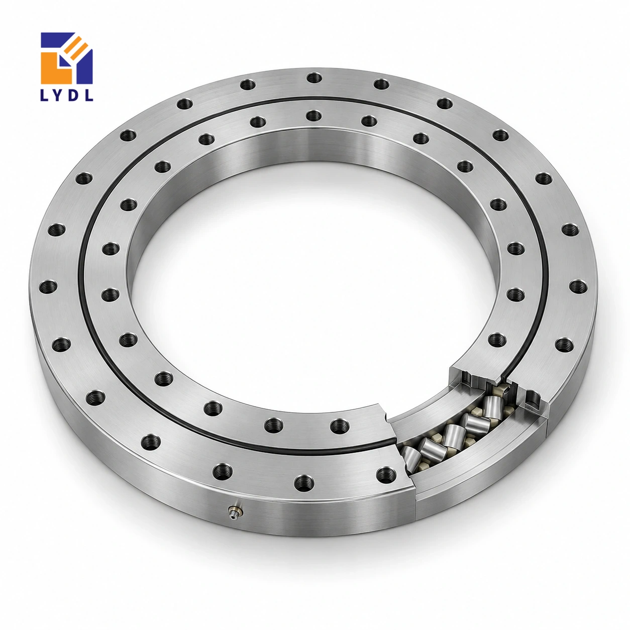
The XU160260 cross roller slewing bearing reference measures 191 × 329 × 46 mm and has no integral drive teeth. Twenty fixing positions on each ring connect it to the surrounding structure, making flange design and the chosen external drive central to the selection.
XU160260 original-reference geometry: Catalogue 404, pp. 90–93. LYDL supply follows its accepted drawing.
XU specification tables · Family technical reference
| Bore (mm) | Outside (mm) | Height H (mm) | Mass ≈ (kg) |
|---|---|---|---|
| 191 | 329 | 46 | 16 |
| Outer PCD La (mm) | Inner PCD Li (mm) | Outer holes na | Inner holes ni | Hole dB (mm) |
|---|---|---|---|---|
| 305 | 215 | 20 | 20 | 14 |
VU200260 is a useful dimensional comparator because its published main envelope is also 191 × 329 × 46 mm. The matching size does not make the products functionally identical. When evaluating a roller-based support for a handling axis, define required angular stiffness, friction at reversal and the combined load cases. Ask for the offered execution and its applicable ratings before deciding whether an existing ball-bearing design can retain its mating components.
The 305 mm outer and 215 mm inner fixing circles should be drawn with their own datums and screw details. Inspect the housing after fabrication; welding distortion must be resolved before using the bearing as an assembly alignment tool.
A wrist can carry a tool whose centre of gravity shifts when the fingers open. Include the open and closed arrangements, together with the load held between them. Consider whether the emergency stop occurs before or after the wrist changes orientation. These situations need not produce the same moment direction.
State how often the mechanism reverses and how it rests between cycles. The bearing proposal can then be reviewed against the actual sequence instead of a single maximum weight.
The XU160260 dimensions describe several different interfaces. Bore 191 mm and outside diameter 329 mm set the basic radial envelope; overall H = 46 mm sets the bearing's axial reference. Fixing circles La = 305 mm and Li = 215 mm locate the outer and inner attachment patterns, rather than the free opening or roller diameter. The reference lists 20 fixing positions on each ring. A circle and a count do not fully describe a hole: seat details, thread engagement and angular orientation still belong on the accepted drawing. Approximate mass 16 kg is a component property, not an approved payload. Reading these fields separately helps prevent a correct catalogue number being transferred to the wrong feature of a mating plate.
A handling wrist may be selected to improve access, reduce package size or address an observed movement under load. State which objective applies before comparing bearing principles. Identify the point on the gripper or tool where the required behaviour is judged. Movement there can include bending of the wrist frame, deformation of the support and response of the drive as well as the bearing arrangement.
The same-envelope VU200260 comparison is useful for studying retained machine interfaces. It does not establish equal internal condition or operating behaviour. Keep the dimensional overlay separate from the required system result. Ask for the actual offered execution and applicable information for the task, with a defined measurement condition. If the current wrist has a problem, describe its direction, load and stage of the cycle. This can prevent a nominally convenient replacement from being chosen without evidence that it addresses the relevant source of movement.
Show the open and closed finger positions, the carried part and any attached tooling. Locate each centre of gravity relative to the ring plane. A gripper can change its mass distribution and force directions while the payload remains the same. Record whether rotation occurs before, during or after that change in configuration.
Include horizontal acceleration, cable or hose reactions and any force from engaging the part with another machine element. An emergency stop needs its actual payload orientation and deceleration description rather than being folded into an unspecified overload factor. Identify the operating combinations that the machine permits. If a future tool is intended, show its independent case instead of assuming a heavier tool is always the governing one. This information creates a repeatable selection basis for the wrist assembly. It does not assign a capacity to the ring from the 191 mm bore, its height or its fixing-hole count.
The ungeared reference leaves the transmission to the machine designer. Draw the coupling, pulley or arm that applies motion, including its support and the point at which the reaction enters the frame. Keep its alignment features visible beside the bearing pilots. A layout that fits the nominal ring envelope may still leave the drive incorrectly positioned after an adapter is introduced.
Review the twenty-position connections with the actual frame sections and any service cutouts. Check both tool access and screw withdrawal when the drive is installed. Identify the order in which the upper plate, ring and central services are assembled. Inspect the final seating after fabrication steps that can change its shape. The bearing connection should secure a prepared interface, rather than straighten a welded frame or pull a tight unknown pilot into place. These practical details make the offered drawing useful to manufacturing and reduce ambiguity when the wrist is serviced later.
An enquiry should identify the model and the mating drawing, then describe the required cycle and the relevant load cases. Include the proposed drive arrangement and the acceptable response at the working point. If dimensional and running checks are requested, specify their support conditions and the offered drawing features to which they apply.
At receiving, compare the component identity with the approved proposal and retain any supplied inspection record. Keep the ring protected until the wrist frame and tools are ready for assembly. During commissioning, record the gripper configuration and service routing used for the check. A change in cable restraint or finger extension can otherwise make later observations difficult to compare. Preserve adapter and bracket revisions with the bearing information. The application photograph illustrates a possible field of use; it does not document a test of this exact wrist. The actual supplied execution and the completed equipment must each be assessed against their own agreed requirements.
For an initial dimensional shortlist, place XU160260 (191 × 329 × 46 mm) beside XU080264 (215.9 × 311 × 25.4 mm) and XU120222 (140 × 300 × 36 mm). These nearby requested references provide a useful envelope comparison, not a sequence of increasing approved load ratings. Compare their actual bolt circles and support faces before deciding which deserves a detailed drawing review. A smaller bore can conflict with the service route, while a different outside diameter changes the available backing annulus. Retain the complete model in every enquiry so a proposal is tied to the intended row. Only the accepted execution and application assessment can resolve the final choice.
A powered handling wrist can be assessed around this reference when the payload centre shifts with gripper orientation. Review cable reaction and emergency deceleration as distinct inputs.

Discuss dimensional inspection after the mating design is established. Request packaging that supports the complete ring and keeps lifting or strapping forces away from seals and vulnerable edges.

Both references list 191 × 329 × 46 mm. Contact principle, supplied clearances and application limits still require separate assessment.
The reference shows twenty fixing positions per ring, located on 305 mm and 215 mm circles.
This XU model is ungeared. An internal-tooth solution belongs to a different family and requires a separate layout review.
Yes. Provide deceleration and payload position so transient forces and moments can be considered with the normal cycle.
Do not rely on fastening to correct structural distortion. Inspect and prepare the seating surfaces before mounting the bearing.
Roller interface comparison: XSU series. Ball-contact option: VU range.
Quote XU160260 with the wrist load cases, drive arrangement and target deflection, including the emergency-stop condition.