

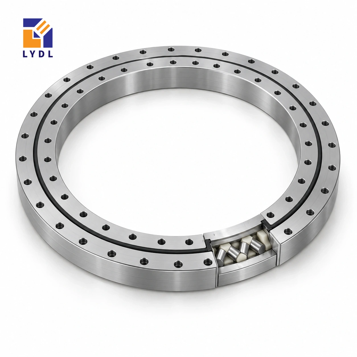
The XSU140414 cross roller slewing bearing is an ungeared series 14 reference measuring 344 × 484 × 56 mm. It should be compared with the smaller-section XSU08 family by its complete envelope and mounting arrangement, rather than by the nearby model numbers.
XSU140414: LYDL dimensions; height reference, Catalogue 404 pp. 86–87. Supply is subject to the accepted LYDL drawing.
XSU specification tables · Family technical reference
| Bore (mm) | Outside (mm) | Height H (mm) | Mass ≈ (kg) |
|---|---|---|---|
| 344 | 484 | 56 | 28 |
| Outer PCD La (mm) | Inner PCD Li (mm) | Outer holes na | Inner holes ni |
|---|---|---|---|
| 460 | 368 | 24 | 24 |
XSU080398 has a 360 mm bore and 25.4 mm height, whereas XSU140414 has a smaller 344 mm bore but a much taller 56 mm reference section. The numeric sequence does not describe a simple linear size progression. Check centre clearance and available axial space independently, then review the twenty-four-position ring connections. Any move between these groups requires a new support and drive-interface assessment.
The outer fixing circle is 460 mm and the inner circle 368 mm. Verify the centring shoulders and screw details before finalising the housing; mounting circles alone do not define the complete interface.
Begin the comparison by sorting constraints into central clearance, axial room and connection geometry. The series 08 and series 14 references satisfy these constraints differently, so an increase in model number should not drive the choice. Next, describe the table task: how the load is applied, what movement is required and where displacement is measured. Only then compare offered execution data.
This sequence avoids treating the taller section as an automatic answer to an unspecified rigidity problem. If the machine already uses XSU08, show how the new axial stack would affect drive alignment, station height and guards. Those consequences belong to the conversion study rather than being left until installation.
The XSU140414 dimensions describe several different interfaces. Bore 344 mm and outside diameter 484 mm set the basic radial envelope; overall H = 56 mm sets the bearing's axial reference. Fixing circles La = 460 mm and Li = 368 mm locate the outer and inner attachment patterns, rather than the free opening or roller diameter. The reference lists 24 fixing positions on each ring. A circle and a count do not fully describe a hole: seat details, thread engagement and angular orientation still belong on the accepted drawing. Approximate mass 28 kg is a component property, not an approved payload. Reading these fields separately helps prevent a correct catalogue number being transferred to the wrong feature of a mating plate.
The transition from XSU080398 to this reference changes the layout in several directions. The bore decreases from 360 mm to 344 mm, the outside diameter increases from 435 mm to 484 mm, and the reference height rises from 25.4 mm to 56 mm. Treat these as independent equipment constraints. A platform chosen to clear a fixed central body may find the smaller opening decisive even when the larger support footprint appears attractive.
Place both arrangements on the same section and mark working height, drive position and service access. Identify whether any adapter preserves the existing station geometry. Then compare the offered executions against the actual task. Neither a taller package nor a change in series number establishes a load capacity, stiffness value or precision class. The geometric comparison is useful because it exposes where a redesign may be required before purchasing the bearing or machining the mating plates.
Show the upright frame and payload with their centres of gravity and relevant force application points. A side force at the top of the frame can create a moment that is not apparent from total weight. Include guide reactions, manual loading and any process contact during dwell. State which orientations and tooling sets are permitted.
For indexing, identify the moving mass distribution, angular travel and acceleration. Keep the drive reaction visible on the base drawing because the transmission is separate from this ungeared ring. The frame and supporting plates contribute to the movement measured at the payload. Define the output requirement at a useful working datum rather than assigning all displacement to the bearing. If an existing machine motivates the enquiry, provide observations under a repeatable load and approach direction. These details support a proposal tied to a measurable equipment need.
The 460 mm outer and 368 mm inner fixing circles belong to the connection geometry, not the free opening. Add the actual screw details and centring shoulders from the offered drawing. Check every tool path with the frame, drive and central services present. Plan how a fastener is withdrawn and how the upper structure is supported during removal.
Review local sections beneath the fixing annuli, including pockets, ribs and access openings. A substantial-looking base can still have an unsupported region near a connection. Inspect its prepared seating after fabrication operations that may change geometry. Document the support condition where it affects measurement. The ring should be installed onto a defined interface. It should not serve as a tool for forcing an uncertain pilot or distorted welded flange into alignment during tightening.
Provide the model, mating drawing and upright-frame load cases together. Specify the required equipment behaviour and distinguish component inspection from the installed-platform test. If running accuracy or clearance is important, ask for the offered execution and an agreed method of checking it instead of adopting a numerical entry from an unrelated reference.
Identify the actual contamination, cleaning and idle environment. Discuss protection for storage and transport and separate loose frame hardware from the machined ring surfaces. At receiving, retain identity and drawing revision with the inspection information. During commissioning, record the tooling set and drive arrangement used for the baseline observation. Keeping these documents together makes later spare ordering and troubleshooting more precise. The photographs illustrate the series and representative applications; they do not certify this exact model's performance in the proposed machine.
XSU140544 expands the opening from 344 to 474 mm and the outer envelope from 484 to 614 mm while retaining a nominal 56 mm height. The fixing count changes from twenty-four to thirty-two positions per ring. If an upright frame requires additional central space, compare its actual lower bracket and services on both rings before deciding that the larger reference solves the interference.
The wider pattern changes where the base and moving plate require backing. It also changes access around the frame. Keeping a working-height allowance is useful, but it does not preserve a locating shoulder, attachment pattern or completed support behaviour. Select the candidate whose actual interfaces suit the structure, then submit the frame force cases and motion to obtain a drawing-based proposal.
A handling turntable carrying an offset upright frame can be assessed around this reference. Include frame flexibility and lateral process forces as well as the weight acting downward.

Define the geometric and functional acceptance requirements for the offered configuration. Use transport support that protects the mounting faces and separates the ring from projecting fixture components.

The families have different sections. XSU140414 has a 344 mm bore and 56 mm height; XSU080398 has a 360 mm bore and 25.4 mm height.
The reference envelope is 344 mm bore, 484 mm outside diameter and 56 mm overall height.
This XSU reference is ungeared. Compare XSA or XSI when the machine layout calls for integral external or internal teeth.
The cited nominal circles are 460 mm and 368 mm, with twenty-four positions on each ring. Obtain the full centring and hole drawing.
The frame and bearing contribute to total angular displacement. A bearing-only requirement cannot describe the complete loaded assembly.
Other ungeared rollers: XU series. Internal-drive layout: XSI range.
Quote XSU140414 with the upright-frame section, available axial space and required angular stiffness.