

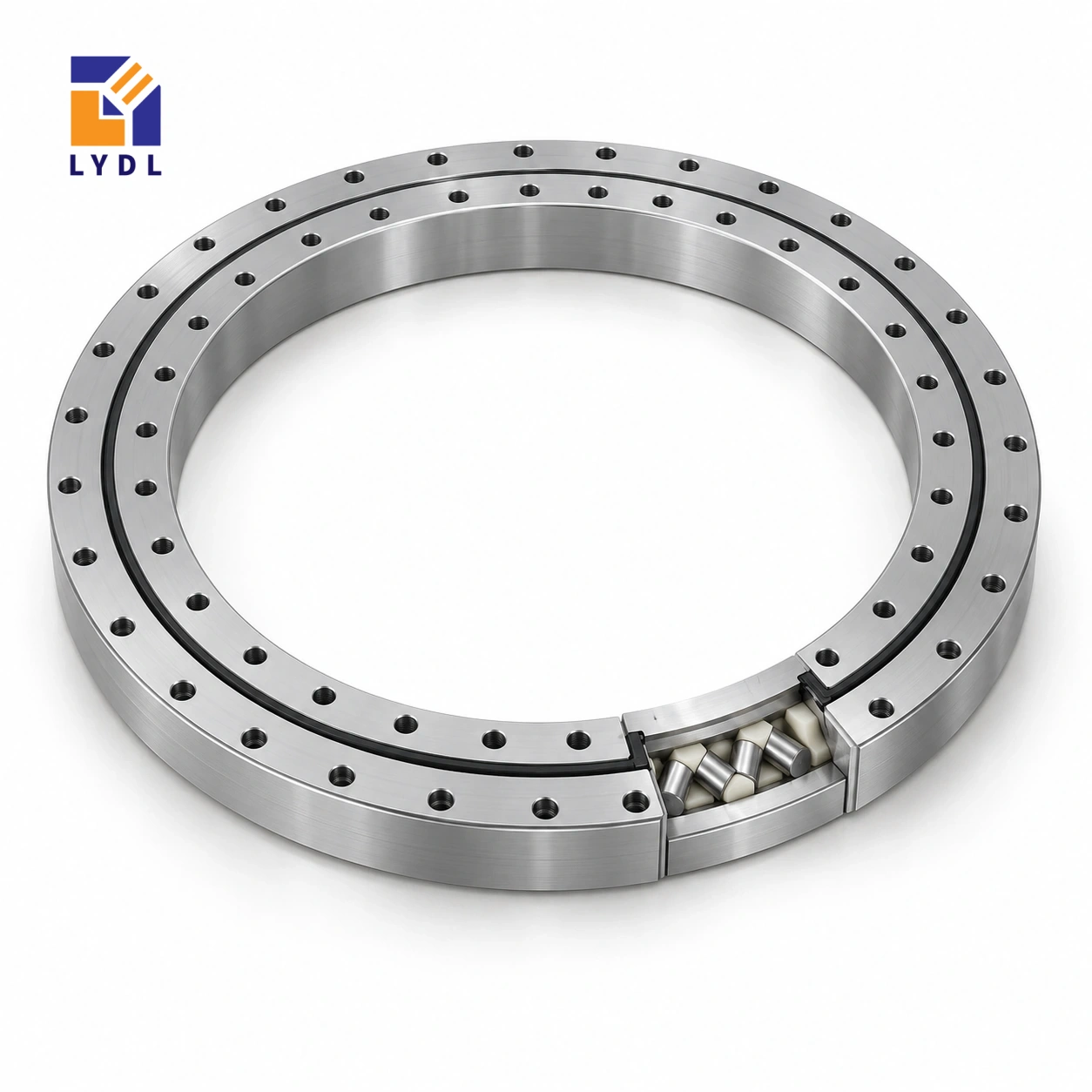
XSU080188 is a gearless crossed roller bearing reference measuring 150 × 225 × 25.4 mm. It keeps the shallow XSU08 height while providing a larger centre opening than XSU080168 and a different sixteen-position fixing arrangement.
XSU080188: LYDL dimensions; height reference, KSX pp. 54–55. Supply is subject to the accepted LYDL drawing.
XSU specification tables · Family technical reference
| Bore (mm) | Outside (mm) | Height H (mm) | Mass ≈ (kg) |
|---|---|---|---|
| 150 | 225 | 25.4 | 3.7 |
| Outer PCD La (mm) | Inner PCD Li (mm) | Outer holes na | Inner holes ni |
|---|---|---|---|
| 210 | 165 | 16 | 16 |
Moving from the 130 mm-bore reference to this 150 mm opening also moves the mounting circles to 210 mm and 165 mm. The hole count rises from twelve to sixteen per ring, so a simple enlarged pilot is not a complete conversion. Check angular positions, screw-head space and material remaining between nearby machined features. A family relationship helps narrow the search but does not preserve an existing fixture interface.
Plan the fastening sequence around the sixteen positions and make the inner screws accessible after service lines are installed. Check seating cleanliness before the final attachment, because small trapped debris can tilt the flange.
When adapting a previous twelve-position plate, do not assume new holes can simply be inserted between the old ones. Check residual wall thickness, abandoned holes, dowels and nearby slots on the actual plate. An adapter may be a better engineering proposal, but its seating and axial effect still need definition. Document which component provides concentric location.
The change from twelve to sixteen positions affects the connection layout, while the operating loads must be assessed independently of that hole-count increase.
The XSU080188 dimensions describe several different interfaces. Bore 150 mm and outside diameter 225 mm set the basic radial envelope; overall H = 25.4 mm sets the bearing's axial reference. Fixing circles La = 210 mm and Li = 165 mm locate the outer and inner attachment patterns, rather than the free opening or roller diameter. The reference lists 16 fixing positions on each ring. A circle and a count do not fully describe a hole: seat details, thread engagement and angular orientation still belong on the accepted drawing. Approximate mass 3.7 kg is a component property, not an approved payload. Reading these fields separately helps prevent a correct catalogue number being transferred to the wrong feature of a mating plate.
A sixteen-position connection needs its own plate drawing even when the surrounding machine already uses another XSU08 size. Overlay the proposed pattern on the existing component with all old holes, dowels, slots and pockets shown. Check the local material at each new attachment instead of assuming that an enlarged centre opening and extra holes complete the conversion.
The 210 mm and 165 mm fixing circles should be located from the same equipment datum as the workpiece nest. Establish the pilot arrangement from the offered bearing drawing and identify which features are responsible for concentric location. If an adapter is proposed, it needs a defined locating and fastening interface on both sides. Include its thickness in the working-height stack and show how the drive alignment is retained.
Review tool access after the pneumatic feed and guards are installed. A conversion can preserve the product position but make the inner screws difficult to remove. Decide which parts are detached during service and how the rotating plate is supported then. These questions distinguish a workable retrofit from a dimensional coincidence and give the supplier a clear interface to assess.
Draw the nest with the part correctly seated and with the clamps in their operating positions. Show forces at their real heights rather than placing every reaction at the bearing axis. State whether the part is guided or supported by another component during loading. A short contact with a transfer guide can differ from the gravity load that remains during rotation.
Include the empty fixture and actuator bodies in the moving mass distribution. Specify the angular stroke, acceleration and reversal pattern. If a misloaded part is a relevant foreseeable condition, describe the approved recovery action and its associated forces separately. Do not label an undefined overload margin as a substitute for those observations.
For the central services, identify what rotates, what remains fixed and where each line is restrained. The 150 mm bore reference does not guarantee space for connectors, tools or the bending path of a hose. Check the installed service envelope and the temporary route used during assembly. This makes the equipment duty and access constraints visible in the same proposal, rather than leaving them to be resolved after the bearing and mating plates have been ordered.
Before ordering a sample, identify the bearing and adapter revisions and state which mating features will be checked. Ask for the actual offered LYDL execution and the inspection information relevant to it. Original reference data should remain identifiable as comparison information, rather than being copied into a delivery guarantee without agreement.
Define the first-article fit review before releasing all replacement plates for manufacture. Record which surfaces locate the assembly and the condition in which rotation is assessed. If the station requires product presentation accuracy, specify its measurement point, fixture configuration and loading state. That test includes the assembled equipment, whereas receiving inspection checks the supplied component against its own documentation.
Protect the ring and adapter faces independently in the shipment and separate loose fasteners or pneumatic fittings. Preserve identification after unpacking, including any approved deviation from the previous machine arrangement. During commissioning, note the sequence in which the drive, feed and tooling are added. Retaining these observations with the original conversion drawing makes later spare ordering and troubleshooting more precise. It also avoids repeating a successful fit from memory while overlooking a critical change in axial height or service access.
If the pneumatic nest needs more central room, XSU080218 changes the bore from 150 to 180 mm and the outer envelope from 225 to 255 mm. Its twenty positions per ring replace the sixteen listed here. Overall reference height remains 25.4 mm. Check whether the larger opening is needed by the actuator body, connector installation or tool access; those are different constraints and should be drawn separately.
A retained plate must be examined with all its existing features visible. Adding a new pattern near an old hole or lightening pocket may leave a different supporting section from the original design. A favourable bore comparison cannot approve that conversion. Locate the flange, nest and actuator from the same documented equipment datums.
Choose a dimensional candidate only after showing the pneumatic lines in their restrained and service positions. Their connectors may control the practical opening more than the cylinder itself. Provide the selected interface and duty to LYDL, then resolve the actual supplied pilot, connection and sealing details. The nominal comparison does not establish equivalent clearance, capacity or fixture presentation accuracy. Preserve the accepted conversion drawing with the first-article record.
An assembly nest that rotates around a pneumatic feed is one possible design example. Provide clamp reactions at each nest orientation and include forces applied during a misloaded-part recovery.

Request the datum and test condition with any rotation check. Separate the ring from feed fittings in the shipping package to protect the bore and seal area.

Its bore increases to 150 mm, outside diameter to 225 mm and fixing count to sixteen per ring; the reference height remains 25.4 mm.
The cited patterns differ. Compare the 210 mm and 165 mm circles and their sixteen positions before considering an adapter.
No. It is the approximate bearing reference mass. Add the nest, drive, fixtures and payload for the moving assembly.
If recovery or clamping creates foreseeable additional forces, describe them separately from the regular cycle so their implications can be assessed.
Possible contributors include seating distortion, contamination and assembly interference. Compare the mounted condition with the agreed inspection baseline.
Other ungeared rollers: XU series. Internal-drive layout: XSI range.
For XSU080188, attach the sixteen-hole flange layout and the pneumatic-feed section to the enquiry.