

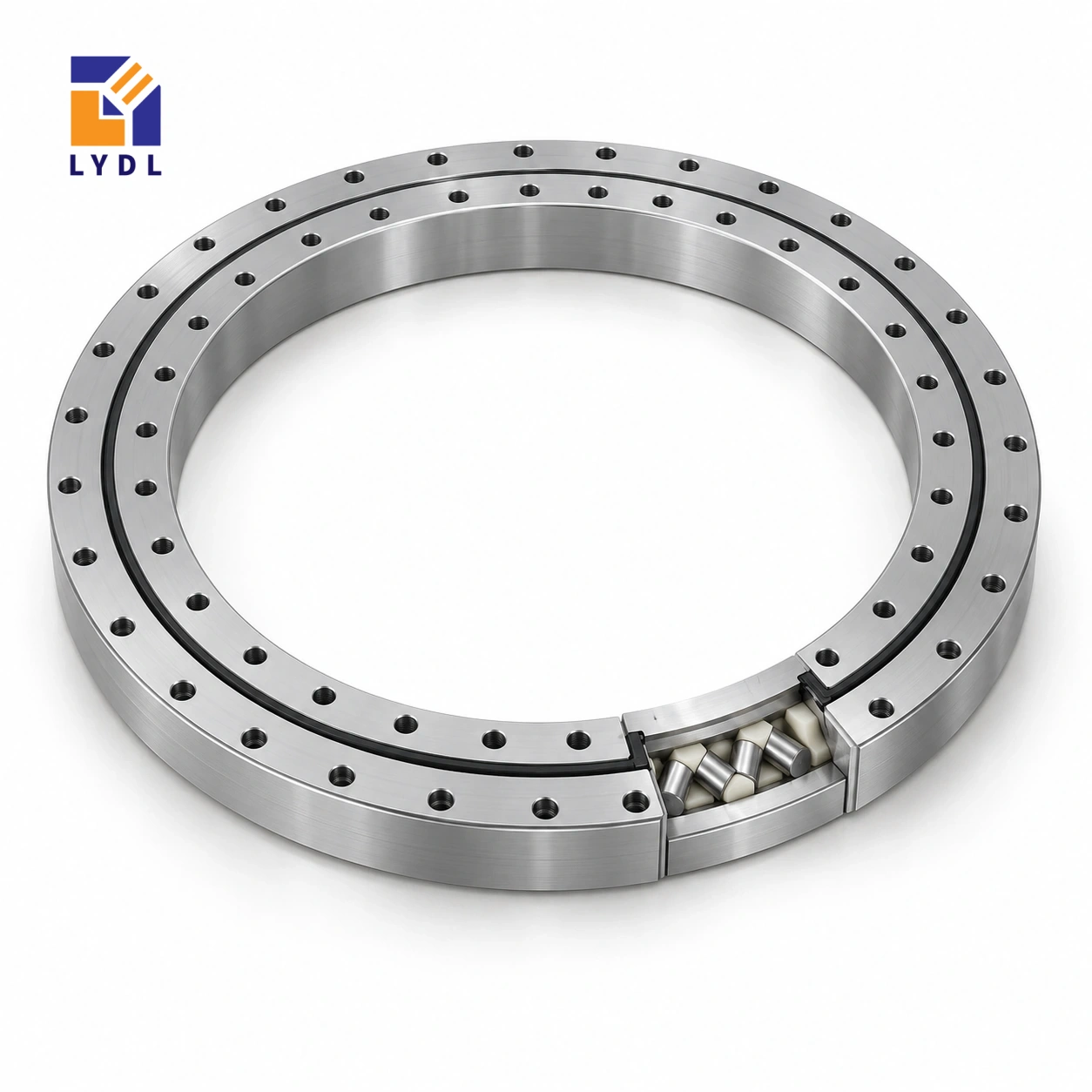
The XSU080168 cross roller slewing bearing is an ungeared series 08 reference with a 130 mm bore and 205 mm outside diameter. A 25.4 mm reference height allows an initial low-profile layout, while the ring connections and surrounding plate determine the practical assembly.
XSU080168: LYDL dimensions; height reference, KSX pp. 54–55. Supply is subject to the accepted LYDL drawing.
XSU specification tables · Family technical reference
| Bore (mm) | Outside (mm) | Height H (mm) | Mass ≈ (kg) |
|---|---|---|---|
| 130 | 205 | 25.4 | 3.3 |
| Outer PCD La (mm) | Inner PCD Li (mm) | Outer holes na | Inner holes ni |
|---|---|---|---|
| 190 | 145 | 12 | 12 |
The first size in this requested XSU08 group has twelve fixing positions per ring. Its 190 mm outer circle and 145 mm inner circle should be checked against the fixture plate before a central actuator is selected. Make room for screw installation as well as for the actuator body. A compact arrangement can become difficult to service if a central valve, rotary union or bracket blocks the inner connection after final assembly.
Use the nominal envelope to establish space, then obtain the detailed hole and pilot drawing. Define which flange is fixed and which rotates; the direction of external loading follows that equipment arrangement.
Draw the actual tightening tool beside the inner connection, including its handle or driver body. A screw visible in a section is not necessarily reachable once the actuator is present. Decide whether the actuator is removable independently of the rotating plate and whether its services can be disconnected without pulling on fittings. Include the intended replacement sequence in the equipment documentation.
This is particularly useful for a compact station whose spare space disappears quickly as sensors and guards are added.
The XSU080168 dimensions describe several different interfaces. Bore 130 mm and outside diameter 205 mm set the basic radial envelope; overall H = 25.4 mm sets the bearing's axial reference. Fixing circles La = 190 mm and Li = 145 mm locate the outer and inner attachment patterns, rather than the free opening or roller diameter. The reference lists 12 fixing positions on each ring. A circle and a count do not fully describe a hole: seat details, thread engagement and angular orientation still belong on the accepted drawing. Approximate mass 3.3 kg is a component property, not an approved payload. Reading these fields separately helps prevent a correct catalogue number being transferred to the wrong feature of a mating plate.
Place the actuator, workpiece nest and bearing on one equipment section. Identify which surfaces set the axis and which fasteners clamp the assembly. The 130 mm bore is a useful opening reference, but the actuator may have collars, fittings or a mounting shoulder that occupy more room than its central body. Include these parts in the installed envelope and in the route used to assemble them.
Keep the 145 mm inner fixing circle distinct from the bore. Check whether a driver can reach all twelve inner positions with the actuator in its documented installation state. If the actuator must be removed first, show how it remains supported and how its services are disconnected. Review access to the outer connection after guards and sensors are installed. A compact station can appear generous when represented only by the bare ring, then become difficult to service once those items are added.
Define how a replacement nest is centred on the rotating plate and where its working datum is measured. Adjustable workholding should not rely on unplanned movement at the bearing attachment. These details allow LYDL to review a specific mechanical interface instead of an incomplete arrangement described only by its central clearance.
Separate operator actions from the controlled orienting cycle. A person pressing a component into a stop can apply a force at the edge or above the bearing plane. The subsequent motor movement may carry a smaller, well-centred load. Mark both conditions and identify the approved loading method so the equipment review does not use the normal rotating weight as its only input.
List the nest, actuator hardware that moves, workpiece and drive attachment at their actual locations. State the angular travel, reversals and pauses. If an orientation change occurs while a clamp is engaged, describe the clamp reactions and how the workpiece is supported. A pneumatic or electrical service can also exert a changing reaction through its restraint. Draw that routing if it affects the moving assembly.
The bearing geometry does not provide a maximum manual force or define motor sizing. Those questions need the supplied execution, complete force locations and motion requirement. Identify which configurations are allowed rather than offering an average of several fixtures. This record is also useful when a new nest is introduced later: a similar workpiece mass can still create a different lever arm or inertia distribution.
Choose the features required for component receiving inspection from the accepted supply drawing. Keep the model and revision on the record and identify the support condition used for any running observation. A photograph of a family ring can assist identification, but it does not establish the dimensions or internal condition of the actual supplied item.
For the completed orienter, define a repeatable nest and a named measurement point. Record whether the check is unloaded, carries a representative part or includes a stated contact force. Compare behaviour after seating the ring, after attaching the upper plate and after fitting the drive. Investigate an unexpected change at the stage where it first appears rather than adjusting the motor immediately.
Discuss the actual contamination, cleaning and idle environment when requesting the offered sealing and lubrication execution. Specify shipment protection for the machined faces and keep loose actuator fittings away from the ring. Retain the commissioning configuration with the bearing order so a future spare can reproduce the approved arrangement. Quantity, destination and the mating drawing complete a useful enquiry; an unsupported precision adjective cannot replace those technical details.
A useful comparison for the orienter is XSU080188. Its bore increases from 130 to 150 mm, outside diameter from 205 to 225 mm, and the hole count from twelve to sixteen per ring. Both references retain the nominal 25.4 mm height. Enlarging the opening therefore does not simply enlarge a single cutout: it changes the plate patterns and their surrounding support as well.
Overlay the actuator and nest on both proposals, then identify whether the extra central space solves an actual installation problem. Check the outside boundary against sensors and adjacent stations. For a compact orienter, preserving an existing working plane can be useful, but the common height does not preserve the pilot or screw access. An adapter added for either connection also becomes part of the height stack.
The original source establishes reference geometry, while LYDL must identify the offered execution. Ask for that drawing with the actuator section attached. A comparison of two envelopes can narrow a search; the final technical decision still needs the load locations, motion and desired result at the nest. Record the chosen interface so a later fixture change can be assessed from a defined starting point.
A small workpiece orienter can be studied with this size. Review operator-applied forces during loading and unloading, which may act differently from the controlled motor cycle.

Specify identification and dimensional acceptance for the purchased execution. Individual wrapping and stable support should keep this shallow assembly from being loaded by other shipment contents.

The main envelope is 130 × 205 × 25.4 mm, with approximate mass 3.3 kg in the cited reference data.
The outer fixing circle is 190 mm and the inner circle is 145 mm. Twelve holes are listed for each ring.
No. This is a series 08 reference; XSU140414 has a different envelope and a 56 mm reference height.
Review its load path and connection. Do not assume the bearing opening alone supplies an actuator mounting or carries a service-line reaction.
Inner bolts hidden behind an actuator can obstruct removal. Show the installed tool-access path on the assembly drawing.
Other ungeared rollers: XU series. Internal-drive layout: XSI range.
Describe the actuator envelope, manual loading forces and service access when requesting XSU080168.