

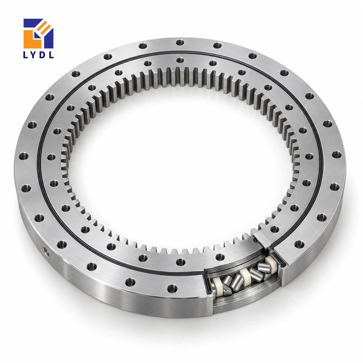
XI200720 is an internally geared crossed roller reference in the LYDL table, measuring 584 × 812 × 58 mm. Its module 8, 75-tooth internal gear and forty-position fixing patterns should be reviewed as two connected but distinct machine interfaces.
XI200720: nominal LYDL listing. INA interchange unverified. Supplied execution requires an agreed drawing.
XI specification tables · Family technical reference
| Bore (mm) | Outside (mm) | Height H (mm) | Mass ≈ (kg) |
|---|---|---|---|
| 584 | 812 | 58 | 84 |
| Outer PCD La (mm) | Inner PCD Li (mm) | Outer holes na | Inner holes ni | Hole dB (mm) | Secondary h (mm) |
|---|---|---|---|---|---|
| 780 | 660 | 40 | 40 | 18 | 51 |
| Pitch d0 (mm) | Module m (mm) | Teeth z | Width b (mm) |
|---|---|---|---|
| 600 | 8 | 75 | 51 |
An internal drive bracket can compete for the same space as the inner-ring fasteners. Start with the 780 mm and 660 mm fixing circles, then add the pinion, bearings and adjustment hardware around the 600 mm gear pitch circle. Check the assembly order before finalising access holes. Modifying a support plate later to reach hidden screws can change its stiffness and invalidate an earlier flange assessment.
The listed 58 mm height, 51 mm secondary height and 51 mm gear width must keep their separate drawing meanings. Match the actual selected execution rather than combining basic and centring dimensions from neighbouring columns.
Write the proposed assembly order as an equipment instruction and test it against the section drawing. Seat the bearing, locate the relevant flange, install fasteners and position the drive components in the intended order, checking the tool envelope at each step. The process may reveal that a pinion support needs to be detachable or that a guard must be split. Include those details before the flange is approved structurally.
A later access cut can change the stiffness that the original calculation assumed. For an indexed packaging machine, describe product loading during acceleration and separately during filling or sealing. Indicate whether a station can remain occupied while neighbouring stations are empty. Provide the maximum allowed combinations rather than a single average platform weight.
If cleaning introduces liquid near the internal mesh, describe its direction and the surrounding enclosure. The model dimensions alone do not establish sealing or cleaning suitability. During commissioning, distinguish setting the gear mesh from checking bearing rotation: each should have a defined condition and acceptance record. A successful drive adjustment does not prove that the supporting plate is free from distortion.
The XI200720 gear row describes internal teeth with module 8 and 75 teeth. Their product is 600 mm, matching the listed nominal pitch diameter. That arithmetic checks the relationship between three entries; it does not calculate a permissible tooth force. The physical outside diameter is 812 mm and the bore is 584 mm, so neither should be replaced by the pitch-circle value in a clearance drawing. Overall height H is 58 mm. Locate the gear face and the two mounting planes from the offered section before positioning a pinion. The tooth form, engagement, quality requirement and supplied material execution remain separate specification items. Keeping these definitions distinct prevents a correct transmission number from being used as the wrong housing dimension.
Describe a handling station through its full loading cycle. Show the positions of arriving parts, grippers and discharge tooling, including periods when only one side is occupied. A balanced completed load does not describe every intermediate state. Include any guide or stop force that acts while a part enters or leaves the platform.
State the number and duration of moves, the intended angle and the distribution of moving mass. If the platform can stop while partially loaded, identify that as an operating case. These details help review the assembly around the 584 mm opening and 812 mm outer envelope. They do not establish a permissible handling capacity from the model number or from the approximate 84 kg component mass.
The row distinguishes H = 58 mm, the separate h entry of 51 mm and a listed gear width b of 51 mm. Preserve those labels when creating an interface drawing. Equal numerical entries for two features do not make the features interchangeable. Obtain the offered section to locate the tooth face, mounting planes and pinion overlap correctly.
The nominal mesh uses module 8 and 75 teeth on a 600 mm pitch circle. Show the pinion bearing support, motor adapter and adjustment space. Include where a protective cover is fixed and how it is removed. A cover should not force a later bracket change that alters the reviewed transmission geometry. The complete offered tooth execution is needed before any permissible force or accuracy statement can be made.
The 780 mm outer and 660 mm inner circles each list forty fixing positions. Overlay those positions on the base and moving plate with their angular relationship to the drive. Check whether a support rib, access panel or central service fitting obstructs any tightening tool. Plan inspection access after the handling equipment is installed.
Describe the manufactured seating, including local pockets and joints between fabricated and machined parts. If the table moves between stations during installation, record the support state used for geometry checks. Tightening should follow the accepted assembly method. The bearing should not become the means of drawing an uncertain flange into shape or forcing a locating feature to fit.
Keep the approved load configurations, tool revisions and drive setting with the commissioning observations. Define an installed check that the maintenance team can repeat under a stated condition. A change in a gripper, stop or production sequence should trigger review against that record rather than an assumption that the original component selection still covers every new task.
Submit XI200720 with the mating drawings and operating schedule when requesting an offer. The LYDL website provides nominal geometry; it does not establish a complete original-brand correspondence for this extended model. Ask for the supply drawing and agreed inspection scope. State the actual dust, cleaning and storage environment so the offered protection and service arrangement can be reviewed against the line conditions.
The XI180865 opening is larger at 736 mm even though its listed overall height is lower at 54 mm; this reference has a 584 mm bore and 58 mm H. Their module 8 gears have 94 and 75 teeth respectively. The model sequence therefore cannot be read as a simple progression of height, opening or ratio.
For the transfer table, overlay the product stations and central services on both candidate sections. Check the twenty-position pattern of XI180865 separately from the forty-position connection here. Preserve the actual partial-occupancy cases in the application enquiry. Select geometry for a defined machine need, then resolve the supplied execution and transmission rather than assuming that a neighbouring XI number is a substitute.
An intermittent packaging turntable provides one application example. Include acceleration, stopped filling forces and uneven product loading, together with the intended cleaning environment.

Agree the gear and seating checks needed for the application. Specify protective packing that keeps cleaning fittings or loose fasteners from contacting tooth flanks.

The LYDL row gives 584 mm bore, 812 mm outside diameter and 58 mm overall height, with approximate mass 84 kg.
Module 8, 75 teeth and 600 mm pitch diameter are listed. Confirm quality, backlash and permissible forces separately.
The reference lists 780 mm outer and 660 mm inner circles, with forty holes per ring and 18 mm hole diameter.
No. Catalogue 404 supports family context; this model’s numerical row comes from LYDL and needs an agreed supply drawing.
The pinion bracket and inner screws may obstruct one another. Planned access can avoid later cuts that weaken the supporting plate.
External gearing: XA series. Standard internal-gear group: XSI range.
Provide XI200720 with an assembly sequence sketch, packaging duty and internal-pinion mounting details.