

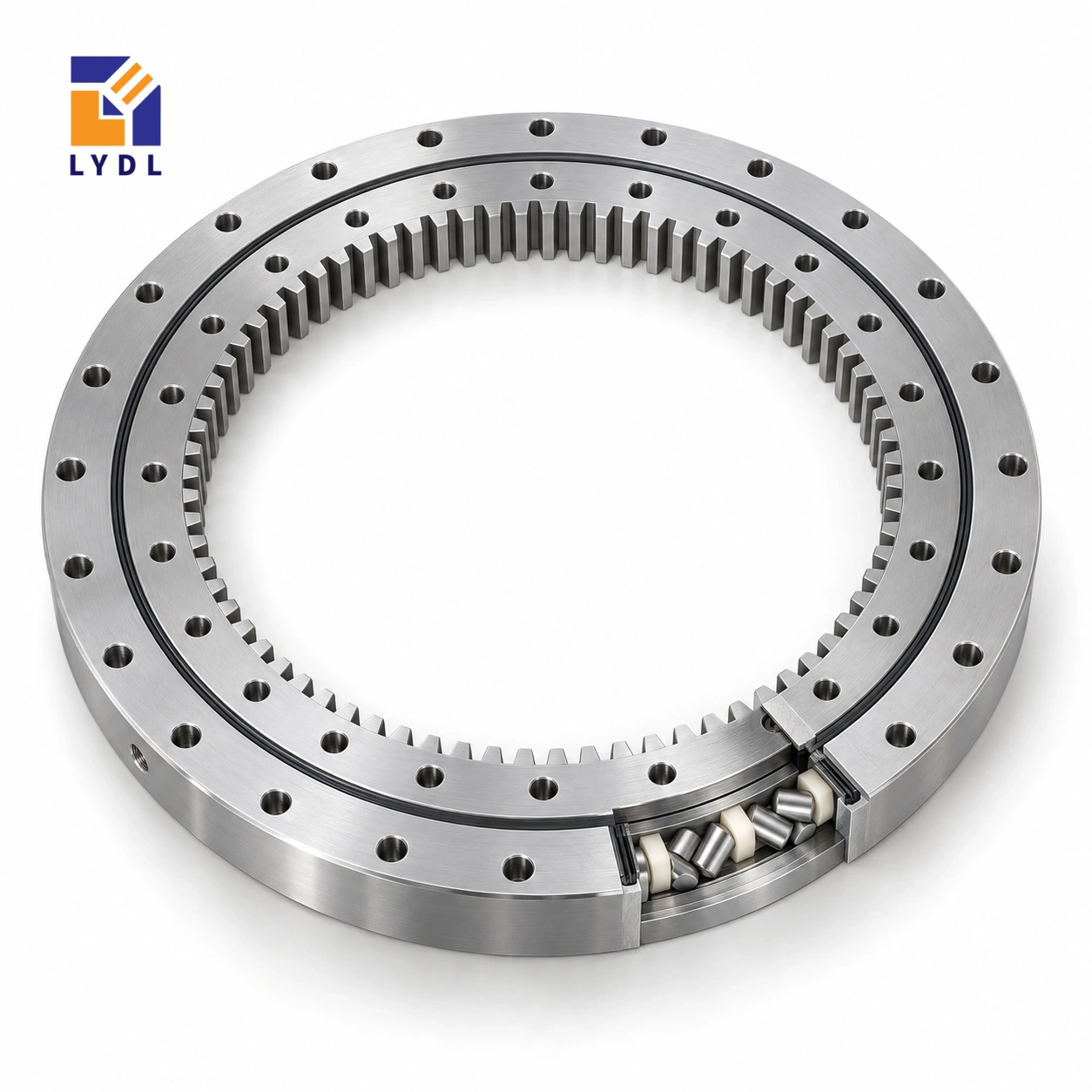
The XI180865 internally geared slewing reference is listed at 736 × 952 × 54 mm. Its module 8 gear has 94 teeth, while the twenty-position fixing circles support a distinctly different flange arrangement from other nearby XI listings.
XI180865: nominal LYDL listing. INA interchange unverified. Supplied execution requires an agreed drawing.
XI specification tables · Family technical reference
| Bore (mm) | Outside (mm) | Height H (mm) | Mass ≈ (kg) |
|---|---|---|---|
| 736 | 952 | 54 | 93 |
| Outer PCD La (mm) | Inner PCD Li (mm) | Outer holes na | Inner holes ni | Hole dB (mm) | Secondary h (mm) |
|---|---|---|---|---|---|
| 920 | 810 | 20 | 20 | 18 | 47 |
| Pitch d0 (mm) | Module m (mm) | Teeth z | Width b (mm) |
|---|---|---|---|
| 752 | 8 | 94 | 47 |
A large central opening may simplify a machine layout, but it leaves an annular support whose stiffness depends on its own section and connections. The 920 mm and 810 mm fixing circles use twenty positions per ring in the LYDL row. Do not copy the forty-hole arrangement from XI200720 or assume the larger diameter means more fasteners. Review unsupported sectors and local bracket forces on the actual plate geometry.
Keep the internal pinion, its adjustment mechanism and the inner fixing tools clear of one another. The listed basic outside diameter is 952 mm; the separate 950 mm centring-execution entry must not replace it without confirming the execution.
A central column may carry pipework, power distribution or tooling that is structurally independent of the rotating platform. Identify which forces pass through the ring and which go directly into the machine base. This distinction prevents double-counting some loads while omitting a bracket reaction that actually reaches the annular flange. Draw the real contact areas around the twenty-position connections, including pockets and access slots.
Where a slot interrupts support, identify how the surrounding plate carries the force to the frame. Do not rely on the nominal circle diameter to describe that path. Check the platform in the most eccentric permitted loading arrangement and during acceleration from that state. On the installation drawing, show the column in the condition used for ring assembly: connectors removed, brackets fitted or fully assembled as appropriate.
The internal pinion requires an additional removal envelope. These geometric checks can rule out a layout before detailed performance comparison, saving a retrofit from reaching the assembly stage with inaccessible screws. They do not, by themselves, establish the bearing’s permissible load or the supplied running accuracy.
The XI180865 gear row describes internal teeth with module 8 and 94 teeth. Their product is 752 mm, matching the listed nominal pitch diameter. That arithmetic checks the relationship between three entries; it does not calculate a permissible tooth force. The physical outside diameter is 952 mm and the bore is 736 mm, so neither should be replaced by the pitch-circle value in a clearance drawing. Overall height H is 54 mm. Locate the gear face and the two mounting planes from the offered section before positioning a pinion. The tooth form, engagement, quality requirement and supplied material execution remain separate specification items. Keeping these definitions distinct prevents a correct transmission number from being used as the wrong housing dimension.
The 736 mm opening may suit a platform surrounding stationary equipment. Begin by drawing that equipment through its full working motion, including doors, connectors and removable modules. Then add the internal pinion, bracket and protective enclosure. The useful centre space is what remains after all these parts and their service motions are included.
Specify which assembly sequence is practical. A stationary column installed first may block access needed to attach the rotating flange; an installed flange may prevent later removal of a central component. Establish those constraints on a sectional layout before choosing the bearing solely for its bore. This reduces the risk of changing a structural cutout after the support arrangement has already been reviewed.
XI180635 also uses module 8, but its 65 teeth differ from the 94 listed here. Keeping a pinion unchanged would therefore not preserve the same ring-to-pinion tooth-count relationship. Evaluate the actual proposed transmission, including motor speed and output movement, rather than treating a common module as a complete drive specification.
The present pitch circle is 752 mm and the external envelope is 952 mm. Locate the mesh on the inside and show the bracket reaction entering the base. Identify the pinion support span and the adjustment method. Ask for the applicable tooth execution and engagement checks for the offered pair. Neither the larger reference nor the common module establishes an allowable tooth load or a guaranteed positioning result.
A wide platform can carry tooling whose mass changes substantially between jobs. List the approved combinations and show their radial and vertical offsets. Include partial occupancy and any processing force at the perimeter. State the motion schedule for each meaningful configuration instead of averaging several different duties into one nominal weight.
The 920 mm and 810 mm fixing circles locate twenty positions per ring. Show flange backing and fastener access around the full circumference, including sectors beside service windows. Review how a removable tool is supported while its connections are released. The mating structure influences the behaviour measured at the working edge, so define the required observation at that edge rather than assigning an unsupported component stiffness.
For this extended XI designation, the published LYDL geometry is the basis of the page and independent original-brand interchange remains unconfirmed. A drawing enquiry should include the existing mating dimensions and the features that cannot change. Resolve the offered ring section, seals and service access in the resulting technical record.
Record the actual identity and revision when the component is received. If inspection or packing evidence is required, agree its scope before supply and distinguish it from the generic illustration shown here. For future spares, retain the pinion information and platform configuration with the bearing record. Repeating only a catalogue-like number can omit the details that determine whether the complete machine can be assembled and serviced.
XI201100 expands the nominal opening to 950 mm and outside diameter to 1200 mm, with 70 mm overall height. It also changes to module 10 and 97 teeth. The present reference uses 736 × 952 × 54 mm with module 8 and 94 teeth. Those differences affect the central drive, flange stack and handling plan together.
If a stationary body motivates the larger candidate, compare its replacement route rather than only its running clearance. Check whether the extra footprint and height fit the installed machine and whether a new pinion support is required. Ask for the individual offered execution of the retained candidate. A dimensional upgrade does not establish original-brand correspondence or approved operating performance.
Record which central module was installed during the access review.
A material-handling platform surrounding a fixed service column is a representative study. Assess eccentric payload positions and the column clearance during installation and maintenance.

Request identification of the offered centring execution and agreed gear measurements. Protect both the broad mounting faces and internal teeth during pallet handling.

The current LYDL row lists twenty, on 920 mm and 810 mm circles. Do not transfer the hole count from another XI model.
The row lists 952 mm as the basic outside diameter. Its separate 950 mm entry belongs to a centring execution.
The listing gives module 8, 94 teeth, 752 mm pitch diameter and 47 mm gear width.
That has not been established for this extended listing. Use the LYDL drawing and application review to assess compatibility.
The column may obstruct inner screws, pinion removal or lifting paths even when operating clearance is sufficient. Show those service movements too.
External gearing: XA series. Standard internal-gear group: XSI range.
Send XI180865 requests with the service-column envelope and twenty-position flange connection drawn explicitly.