

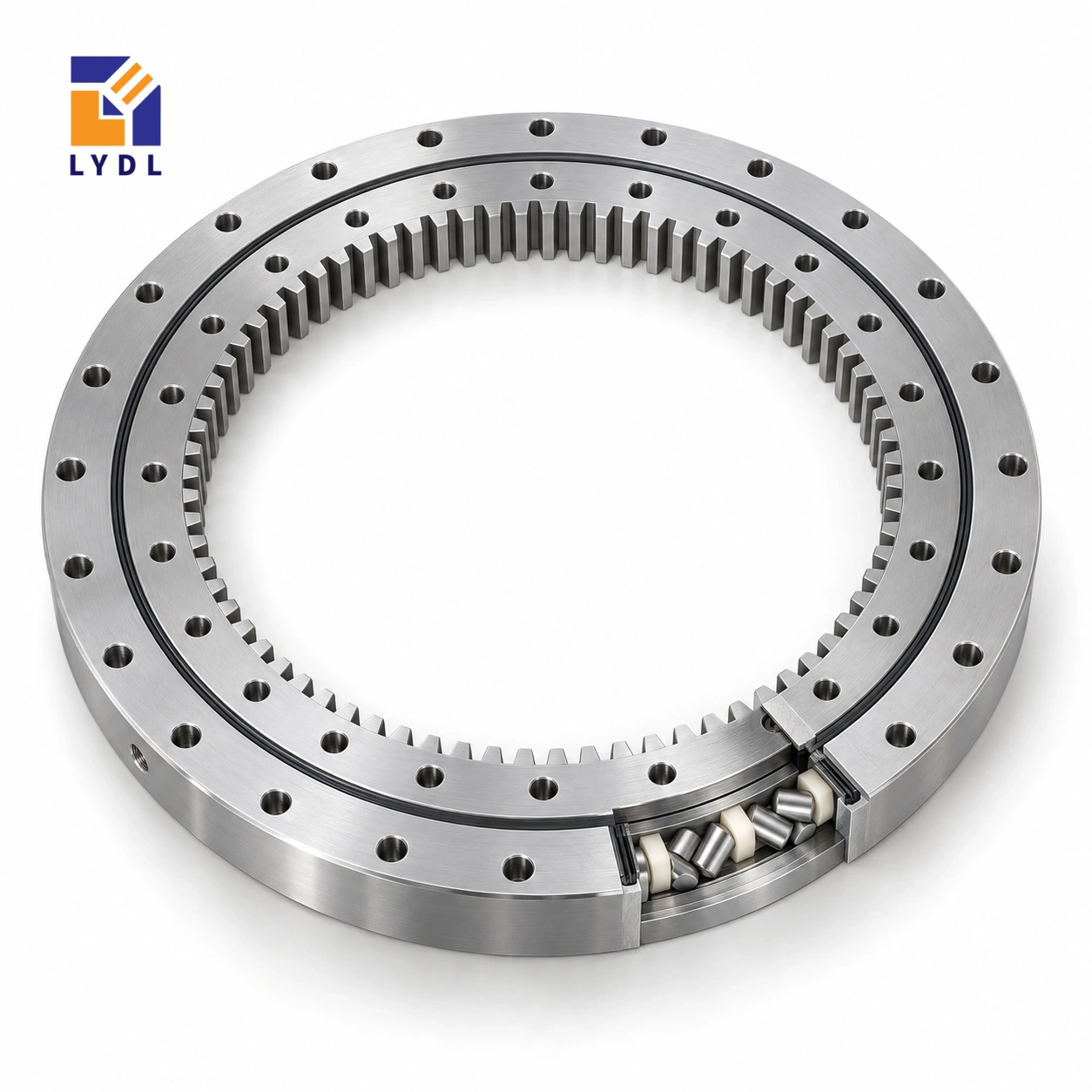
XI120420 is listed by LYDL as an internally geared cross roller reference with a 332 mm bore, 486 mm outside diameter and 39 mm total height. Its module 4, 85-tooth gear offers a different interface from the smaller XI120288 listing.
XI120420: nominal LYDL listing. INA interchange unverified. Supplied execution requires an agreed drawing.
XI specification tables · Family technical reference
| Bore (mm) | Outside (mm) | Height H (mm) | Mass ≈ (kg) |
|---|---|---|---|
| 332 | 486 | 39 | 23 |
| Outer PCD La (mm) | Inner PCD Li (mm) | Outer holes na | Inner holes ni | Hole dB (mm) | Secondary h (mm) |
|---|---|---|---|---|---|
| 462 | 378 | 16 | 16 | 14 | 34 |
| Pitch d0 (mm) | Module m (mm) | Teeth z | Width b (mm) |
|---|---|---|---|
| 340 | 4 | 85 | 34 |
The current series table identifies the requested reference in its final column as XI120420N, alongside an LXII-labelled row. Keep that source relationship visible in the drawing enquiry so the intended product is clear. This extended listing has not been established as an exact standard row in Catalogue 404. Treat its dimensions as LYDL website reference data and obtain the offered drawing, rather than presenting the catalogue link as proof of INA interchangeability.
Sixteen positions per ring are listed on 462 mm and 378 mm fixing circles, with 14 mm hole diameter. Check the pinion bracket and fastener-access paths within the 332 mm opening before finalising the housing.
Create a replacement record with the old component marking, machine drawing number, measured envelope and the LYDL reference row. If an equipment list uses a different prefix from the final-column model reference, preserve both in the enquiry instead of silently treating them as interchangeable names. Ask for the exact designation that will appear on the supply drawing. This avoids ordering a nominally similar ring on the strength of a search result.
On the machine section, mark the inner fixing-tool route and the pinion support separately. Determine whether either part must be removed before the bearing can be lifted. Check the proposed guard against both routes. A hidden screw is a service problem even when its centre lies on the correct circle.
Review a proposed adapter by tracing force transfer through its two connections and the base, rather than checking that its holes align. Finally, state the operating concern that motivates replacement. If the old platform exhibits lost motion, record where it is measured and whether it occurs on reversal, under load or at a particular angle. Those observations help separate transmission behaviour from the bearing proposal.
The XI120420 gear row describes internal teeth with module 4 and 85 teeth. Their product is 340 mm, matching the listed nominal pitch diameter. That arithmetic checks the relationship between three entries; it does not calculate a permissible tooth force. The physical outside diameter is 486 mm and the bore is 332 mm, so neither should be replaced by the pitch-circle value in a clearance drawing. Overall height H is 39 mm. Locate the gear face and the two mounting planes from the offered section before positioning a pinion. The tooth form, engagement, quality requirement and supplied material execution remain separate specification items. Keeping these definitions distinct prevents a correct transmission number from being used as the wrong housing dimension.
A 332 mm bore can be useful around a stationary service column, provided the internal transmission is included in the space study. Place the column, cable bundle, connectors and strain reliefs in a section through the pinion. Check moving and fixed parts throughout the intended rotation. The available opening is an assembly result, not simply the bare-ring bore entered in a table.
Define whether cables twist through a limited angle, pass through a rotary interface or remain entirely stationary. Show how they are replaced after the platform is assembled. A connector that passes through the opening before installation may not be removable later. These service details can determine the preferred ring orientation and motor location before a load calculation or procurement comparison is complete.
With 85 nominal ring teeth and module 4, the row identifies a particular internal gear geometry. Evaluate the proposed pinion against that geometry rather than choosing a motor from a neighbouring model's ratio. Describe the required angular travel, move time, settling period and reversal pattern. Include changes in tooling inertia between product variants.
Keep holding during a process operation separate from accelerating the platform. If a brake or mechanical restraint carries a dwell reaction, show where it acts and how it is controlled. Also identify a credible abnormal stop for the machine review. The product listing offers no permissible emergency torque. Supplying the operating sequence helps the application assessment address the intended equipment instead of treating continuous rotation, intermittent positioning and process holding as equivalent tasks.
The outer circle is 462 mm and the inner circle is 378 mm, with sixteen listed positions on each ring. Overlay the mating patterns on the platform and base. Add counterbores, screw heads and the actual tightening tool. The column may obstruct a tool extension even where the fastener itself fits. Check angular orientation against the drive bracket and service outlet.
Inspect backing beneath the connections for pockets and large access cutouts. Describe any welded construction and the condition in which the seating is measured. A thick plate with an unsupported sector still requires review. The accepted assembly procedure should establish how the ring is seated and secured without using bolt tightening to correct an uncertain locating shoulder or pull a distorted base into place.
Submit a drawing of the service column and pinion bracket with the requested quantity and operating cases. Ask LYDL to identify the offered execution, applicable limits and any inspection evidence available for that offer. The nominal website row does not independently establish an original-brand equivalent for this extended XI reference.
Record open questions as questions, including seal arrangement, lubrication access and the required installed behaviour. At commissioning, document the tooling and cable state used for the initial observation. For later troubleshooting, compare like conditions before attributing a change to the bearing. Keeping the component identity, transmission details and service routing together also makes a future spare enquiry more precise than a model number without its machine context.
The next bore option in this requested XI set is XI160489 at 384 × 562 × 45 mm. It changes from module 4 and 85 teeth here to module 6 and 66 teeth. Enlarging the opening for a service column therefore also changes the proposed pinion interface and the vertical stack.
Mark the column connectors, bracket and working plane on both layouts. Check whether the added opening solves a real installation constraint and whether the larger outside boundary fits the base. The sixteen-position pattern of XI120420 is not carried into the forty-position XI160489 connection. Obtain the individual offered drawing before releasing an adapter; the website rows do not establish a complete original-brand interchange for either extended reference.
A rotary packaging platform with an internally positioned drive is one study case. Include acceleration of the loaded platform and access for clearing the product feed safely.

Agree how the internal gear and flange datums will be checked on the supplied execution. Pack loose pinions separately so they cannot strike the ring teeth.

LYDL currently lists 332 × 486 × 39 mm, approximate mass 23 kg, with 462 mm and 378 mm fixing circles.
No. This listing uses module 4 with 85 teeth and a 340 mm pitch diameter; XI120288 lists 56 teeth.
No exact standard row was established in Catalogue 404 for this package. The page uses the LYDL listing and requires a confirmed supply drawing.
It helps identify the intended source row. The final supplied designation and execution should be written into the accepted order documents.
Provide moving inertia, acceleration, product distribution and abnormal clearing forces when applicable, together with the internal-drive geometry.
External gearing: XA series. Standard internal-gear group: XSI range.
Identify XI120420 and its listed N reference, then attach the mating pinion and flange drawings.