

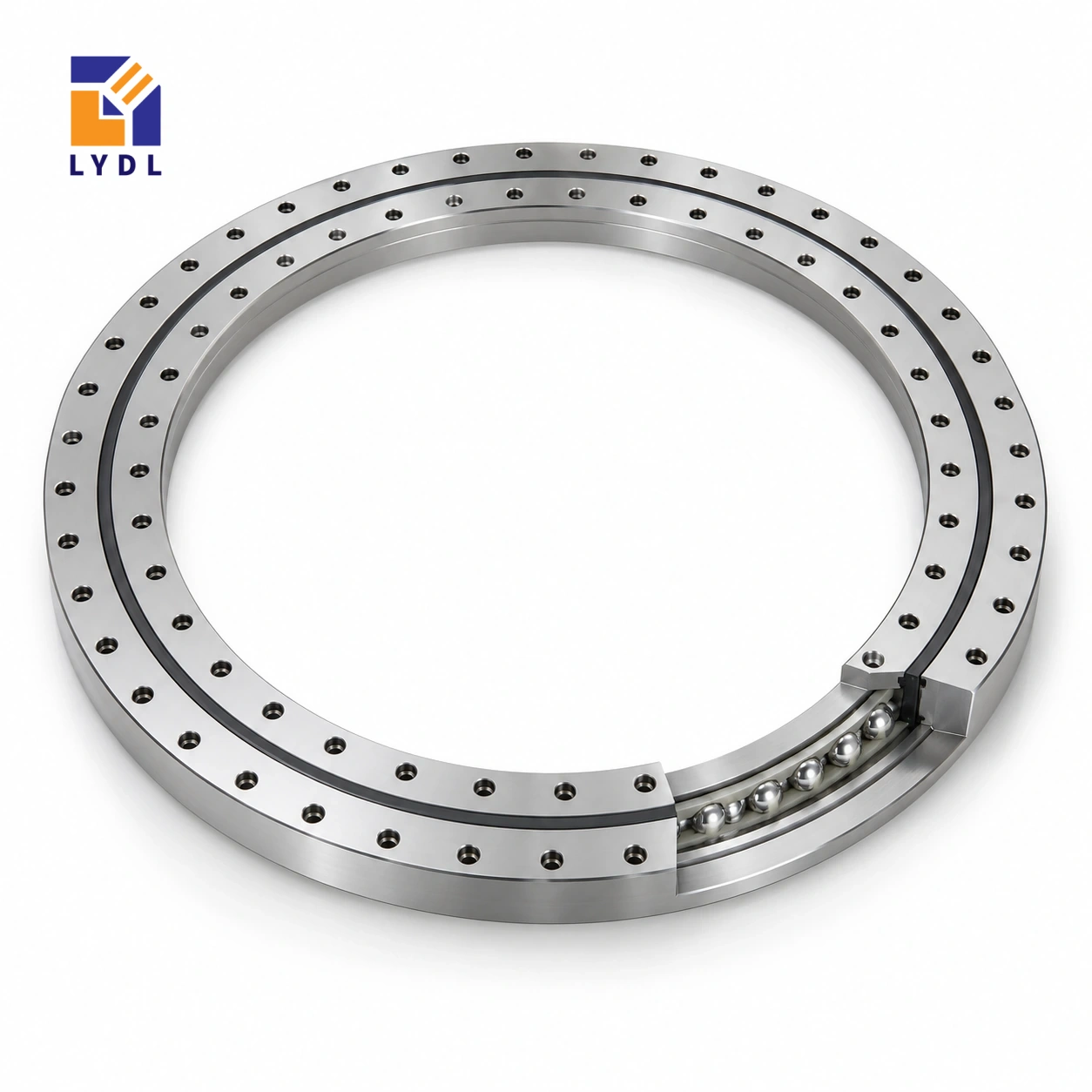
VU250433 is a gearless four-point contact ball reference measuring 344 × 522 × 55 mm in the LYDL table. Twenty outer fixing positions connect this package to the supporting structure, with circle diameters that differ from VU250380.
VU250433: current LYDL nominal table. Confirm the supplied configuration and limits by drawing.
VU specification tables · Family technical reference
| Bore (mm) | Outside (mm) | Height H (mm) | Mass ≈ (kg) |
|---|---|---|---|
| 344 | 522 | 55 | 42 |
| Outer PCD La (mm) | Inner PCD Li (mm) | Outer holes na | Hole dB (mm) | Secondary h (mm) |
|---|---|---|---|---|
| 490 | 376 | 20 | 18 | 50 |
The larger 344 mm bore can alter available service space, but the outer envelope also grows to 522 mm and the fixing circles move to 490 mm and 376 mm. A change intended only to clear a central component therefore requires a new flange review. Compare the available contact annuli and the position of the external drive. The 55 mm height shared with VU250380 does not preserve its radial mounting geometry.
The listed fixing-hole diameter is 18 mm. Confirm the complete inner pattern and centring shoulders, then check that the service component can be installed without blocking bolt tools or the ring-removal path.
Show the column with all installed collars, connectors and support brackets, then draw its removal route. It may fit in operation yet require a larger temporary opening during assembly. Determine which components remain in place when the ring is replaced and how the platform is supported during that operation. Keep the tool-access space around the inner connection visible in the drawing.
Increasing the bore can solve one clearance problem while moving the flange connections, so check the complete arrangement before manufacturing an adapter.
Read VU250433 as a four-point contact ball reference with 344 mm bore, 522 mm outside diameter and 55 mm overall H. The separate h entry is 50 mm; use its labelled drawing feature rather than assuming it describes the whole assembly. The approximate listed mass is 42 kg and supports component handling information, not a payload rating. La = 490 mm locates the outer fixing circle; it is not the outside diameter. A connection also needs its hole form, screw engagement and locating features. Compare those items with the actual machine drawing before releasing mating parts. Values absent from the website row remain unresolved rather than becoming zero. The nominal table helps identify the intended geometry, while the agreed supply drawing defines the purchased execution.
This row lists a 344 mm bore, 522 mm outside diameter and 55 mm overall height. VU250380 has a smaller 275 mm bore and 485 mm outside envelope at the same listed height, while its approximate mass is different. These facts describe geometry and component mass; they do not rank approved operating capacities.
Compare the actual machine constraints: central clearance, support footprint, working stack and connection access. Include the complete drive and any stationary body through the opening. A larger opening may simplify one service route while changing the flange backing and attachment layout. Request application review for the chosen offered execution instead of selecting solely by the apparent size progression.
Place each permitted workpiece and fixture on the table drawing. Show the centre of gravity, radial offset and relevant force heights. Include loading and unloading contacts with guides or stops. A partly loaded state can create a different moment from the completed load and should remain visible in the duty schedule.
For powered movement, give angular travel, timing, acceleration and reversal with the moving mass distribution. Keep process holding distinct from motion. Define the required behaviour at a useful workpiece datum. The plate, joints, drive and four-point ball arrangement contribute to that result. The nominal ring data does not establish a numerical stiffness or positioning accuracy for the handling machine.
The 490 mm outer and 376 mm inner fixing circles list twenty positions with an 18 mm hole entry. Add the actual hole form, seats, screw engagement and locating details from the accepted supply drawing. Confirm the angular relationship required by the machine and check tool access with guards and central services fitted.
Show the real backing beneath both attachment patterns, including pockets and frame connections. Keep overall H = 55 mm distinct from the separate h = 50 mm feature. Define the support condition for seating inspection. An installation should meet a prepared interface rather than use the ring or tightening sequence to force an uncertain flange into alignment.
Because there are no integral teeth, draw the proposed motion input and its support explicitly. Belt tension, friction contact or linkage reaction can add forces at locations different from the payload. Include the actual concept in the component enquiry, together with any holding restraint used during dwell.
Check adjustment and replacement movements after the fixture is installed. A motor can fit in operation while remaining inaccessible beneath an overhanging plate. Identify the guard opening and the tools needed at the bracket and bearing connections. The drive layout, service route and flange support should be reviewed together so a late access change does not alter the accepted structural arrangement.
Ask LYDL for the offered drawing, applicable execution and requested inspection information. The approximately 42 kg listed mass is useful for handling the component but is not a workpiece rating. Plan suitable support during receipt and installation using provisions accepted for the supply.
Separate received-component checks from the completed fixture test and record the load, approach and support state. Keep the accepted tooling and drive revisions with commissioning information. Discuss dust, cleaning and storage when reviewing protection. The shared images offer general context and cannot certify a model-specific test. Future spare enquiries should use the controlled drawing and operating record.
The smaller VU200405 bore is 336 mm, close to the 344 mm opening here, but its outside diameter is 474 mm and H is 46 mm. This VU250433 row occupies 522 mm outside and 55 mm height. Their thirty-position and twenty-position connections also differ. An existing platform can therefore require significant interface work despite the modest bore change.
For the changing-offset fixture, locate the part and tooling on both layouts. Check the extra stack height, access around the central services and the actual annular backing. Include the separate drive and restraint in the comparison. A wider ring envelope does not alter the applied force location unless the surrounding equipment is redesigned.
Use the chosen geometry to request a defined LYDL offer with the applicable ball-contact execution. Ask for review against the real duty and installed observation. The nominal row does not establish a capacity or precision ranking between the candidates. Retain the accepted connection and drive revisions with the component identity for repeat supply.
A material-handling rotary stage surrounding a fixed column is a representative design study. Include payload eccentricity and the force path through any brackets attached near the inner opening.

Agree dimensional identification of the supplied revision and inspect the relevant pilot features. Keep the bore and seating surfaces protected from the fixed-column hardware during shipment.

No. VU250433 lists 490 mm and 376 mm circles; VU250380 lists 453 mm and 307 mm.
The current nominal bore is 344 mm, within a 522 mm outside diameter and 55 mm overall height.
The current LYDL table gives approximate mass 42 kg and twenty outer fixing positions. Hole diameter is listed as 18 mm.
The radial envelope, fixing circles and locating features still differ. Check the complete mating geometry before retaining a housing.
Provide its outer envelope, mounting brackets, assembly path and operating reactions, together with the payload and motion cycle.
Compare roller principles through XU series and XSU range.
For VU250433, attach the central-column envelope and a section through the two mounting plates.