

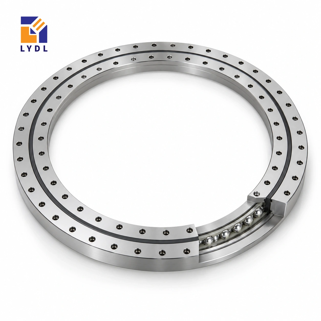
The VU250380 four-point contact ball slewing reference is listed with a 275 mm bore, 485 mm outside diameter and 55 mm height. This ungeared package has a different mounting footprint from nearby VU references with a similar centre opening.
VU250380: current LYDL nominal table. Confirm the supplied configuration and limits by drawing.
VU specification tables · Family technical reference
| Bore (mm) | Outside (mm) | Height H (mm) | Mass ≈ (kg) |
|---|---|---|---|
| 275 | 485 | 55 | 45 |
| Outer PCD La (mm) | Inner PCD Li (mm) | Outer holes na | Hole dB (mm) | Secondary h (mm) |
|---|---|---|---|---|
| 453 | 307 | 16 | 18 | 50 |
A support designed around a roughly 275 mm bore may not extend far enough to back this ring’s fixing region. Draw the actual contact surfaces around the 453 mm outer and 307 mm inner fixing circles. Check flange bending and the local connection to the base, including ribs or welds. The listed mass is useful for handling planning, but should not be used to infer load capacity or replace a complete force and moment assessment.
The current VU row lists sixteen outer positions and 18 mm fixing-hole diameter. Confirm screw engagement, head clearance and all inner attachment details before ordering the machined support plates.
Examine the region directly below the outer and inner fixing circles on a section of the base. A heavy central boss does not necessarily support the annulus where the ring is attached. Identify ribs, pockets and weld transitions near that area and show how the fixture force reaches the machine frame. If the top fixture overhangs, include its offset and clamp reactions.
State the assembly mass separately for handling. These details make the width and weight figures meaningful layout inputs without using either as an unsupported capacity claim.
Read VU250380 as a four-point contact ball reference with 275 mm bore, 485 mm outside diameter and 55 mm overall H. The separate h entry is 50 mm; use its labelled drawing feature rather than assuming it describes the whole assembly. The approximate listed mass is 45 kg and supports component handling information, not a payload rating. La = 453 mm locates the outer fixing circle; it is not the outside diameter. A connection also needs its hole form, screw engagement and locating features. Compare those items with the actual machine drawing before releasing mating parts. Values absent from the website row remain unresolved rather than becoming zero. The nominal table helps identify the intended geometry, while the agreed supply drawing defines the purchased execution.
Show the 275 mm bore and 485 mm outside envelope together with the fixture and base. Include collars or services through the centre and the route needed to install them. The radial package matters to flange backing, while the central opening matters to access. Neither should be replaced by a fixing-circle dimension in the machine layout.
Use the 55 mm overall height in the complete axial stack with adapters and plates. Identify the actual mounting planes from the offered section. Check whether a fixture can be removed independently of the central equipment and whether tools reach both connections. These practical questions should be settled before the supporting parts are manufactured.
The approximately 45 kg listed mass supports planning for receipt, temporary support and installation of the component. Describe the access route and ask for suitable handling provisions for the supplied execution. Do not lift using an unapproved hole, seal feature or local edge. Keep loose hardware from contacting machined surfaces.
That mass does not establish an approved workpiece load. For the application, provide payload and tooling positions, relevant force heights and process reactions. Include the movement schedule with mass distribution. A four-point contact ball designation identifies the contact arrangement but does not supply the offered clearance, precision or numerical stiffness. Those questions require the actual execution and equipment assessment.
The outer circle is 453 mm and the inner 307 mm, with sixteen listed positions and an 18 mm hole entry. Confirm the complete hole form, seats, screw engagement and locating features from the accepted drawing. The same position count on two rings does not make their mating interfaces identical.
Review the actual flange sections beneath both patterns. Include pockets, ribs and connections to the machine frame. Check angular orientation and tool access with the drive installed. Overall H is 55 mm; the separate h entry of 50 mm retains its own feature meaning. Inspect the prepared seating in a defined condition and follow the agreed fastening procedure.
The ring is ungeared, so specify how motion is introduced. Draw the transmission, adjustment and support, including reactions from belt tension, friction contact or a linkage if those are proposed. The same desired torque can be applied through different force paths. Keep their actual locations visible in the equipment drawing.
State angular travel, acceleration, normal reversal and dwell with the moving tooling. If a separate restraint carries a process force, show where and when it acts. Define the required output behaviour at the fixture under a stated condition. The complete assembly contributes to that result, so neither the model designation nor the contact principle can establish the machine outcome alone.
Send the mating sections, duty and requested evidence with the model enquiry. Ask LYDL to identify the offered execution and applicable limits. Agree received-component checks separately from the installed machine observation and retain the conditions with each result. Keep the accepted flange, fixture and drive revisions linked to the bearing identity.
Discuss contamination, cleaning and storage interval when reviewing protection. Pack the component on suitable support and separate loose accessories. The family photo, application montage and packaging illustration provide general context; they do not document testing or shipment of VU250380. A future spare order should refer to the controlled configuration rather than the image or nominal row alone.
VU250433 retains 55 mm overall height but changes the bore from 275 to 344 mm and the outside envelope from 485 to 522 mm. The listed mass decreases from approximately 45 to 42 kg, while the position count increases from sixteen to twenty. This is a useful reminder that larger nominal openings do not create a simple progression of component mass or approved capacity.
Put the intended fixture and central services on both sections. Check which opening is needed by the actual assembly and how the changed fixing circles reach the supporting structure. The screw form, engagement and locating features must be resolved for the chosen offered execution.
If handling is the concern, use the approximate component masses to plan the operation and request appropriate provisions for the delivered rings. If operating behaviour is the concern, submit force locations, motion and the required working-datum result instead. Keep those separate questions clear in the enquiry so the dimensional comparison does not become an unsupported payload recommendation.
A welding-positioner base carrying a compact but heavy fixture is an illustrative case. Record the fixture centre of gravity, clamp forces and proposed electrical return path independently.

Specify the acceptance datums and any agreed running check for the supplied ball-bearing execution. Use a transport base that supports the ring without concentrated contact on seals or small shoulders.

The website gives 55 mm overall height and a separate 50 mm h dimension. Keep those features distinct in the assembly section.
The current LYDL listing gives approximately 45 kg. This is reference bearing mass, not a complete shipped-machine weight.
Use the listed 453 mm outer and 307 mm inner circles, sixteen outer positions and 18 mm hole diameter as drawing-review inputs.
VU140325 has a much smaller outside diameter and lower height. Similar centre openings do not establish the same support footprint.
No capacity claim follows from width alone. The offered execution, support structure and combined-load cases must be assessed.
Compare roller principles through XU series and XSU range.
Send VU250380 with the base cross-section and fixture load locations rather than only the payload mass.