

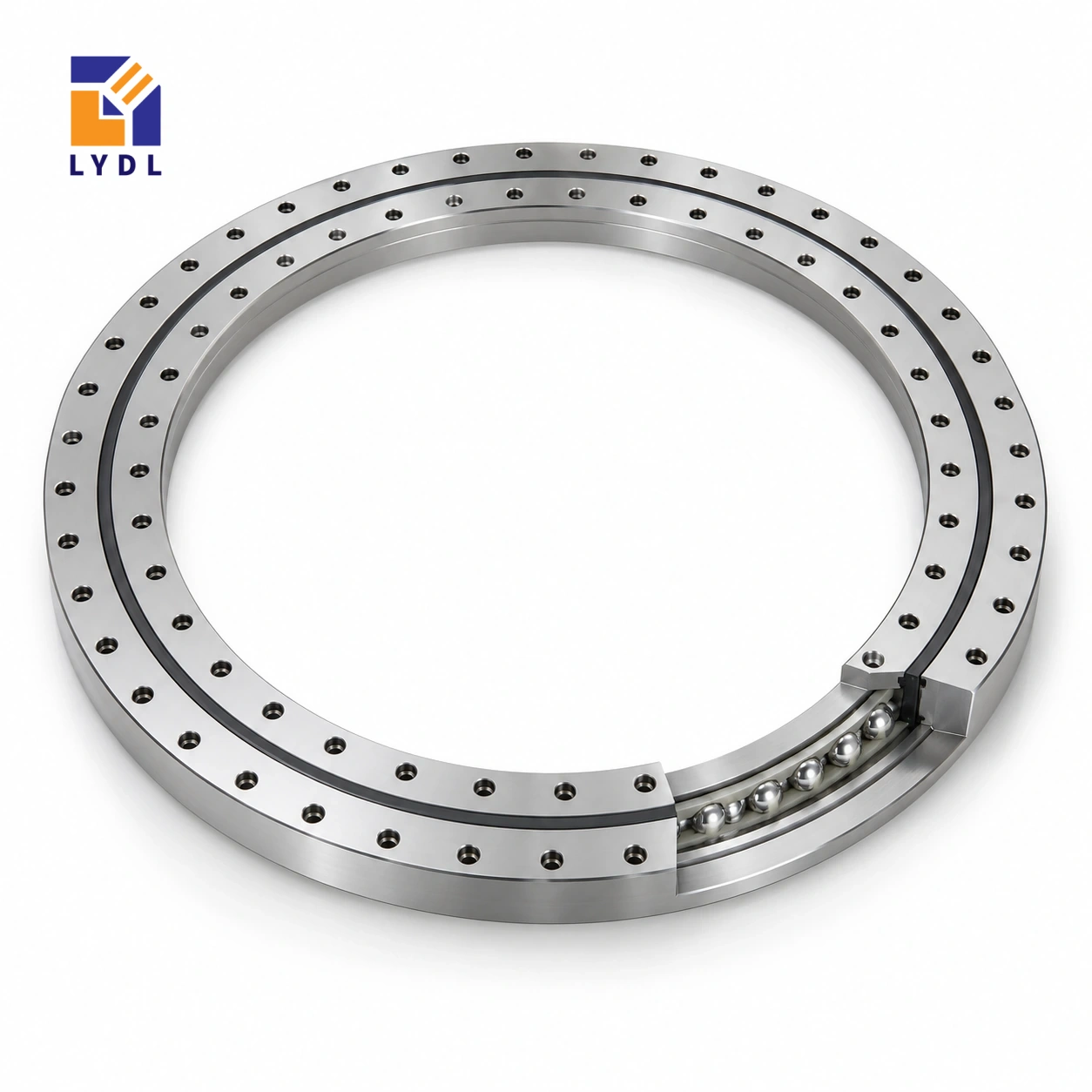
The VU140179 slewing bearing is a gearless four-point contact ball reference measuring 124.5 × 234 × 35 mm. It belongs to the ball-based VU family; a similar-looking roller ring or shared envelope should not obscure that contact arrangement.
VU140179: current LYDL nominal table. Confirm the supplied configuration and limits by drawing.
VU specification tables · Family technical reference
| Bore (mm) | Outside (mm) | Height H (mm) | Mass ≈ (kg) |
|---|---|---|---|
| 124.5 | 234 | 35 | 7 |
| Outer PCD La (mm) | Inner PCD Li (mm) | Outer holes na | Hole dB (mm) | Secondary h (mm) |
|---|---|---|---|---|
| 214 | 144.5 | 12 | 11 | 30 |
XU120179 has the same basic reference envelope, making it a useful crossed roller comparison. A switch between the two needs an assessment of required stiffness, running resistance, clearance and the actual load spectrum. Decide what the fixture must do before comparing ratings or requesting a replacement. An apparently identical mounting package can conceal a different functional requirement, particularly where a measuring arm or offset process tool amplifies small angular movement.
The current VU table lists 214 mm and 144.5 mm fixing circles, twelve outer positions and 11 mm hole diameter. Confirm both ring patterns and locating features on the supplied drawing before making an adapter.
If an existing compact table shows unwanted movement, measure it at a named point and record the applied force. Check whether the movement comes from the support, bracket, fixture or rotary connection. A change from balls to rollers should be considered against that evidence and the offered execution. Keep the interface comparison separate: an envelope match helps layout review but does not diagnose the original problem.
The resulting enquiry should describe both the observed behaviour and the result the finished equipment must achieve.
Read VU140179 as a four-point contact ball reference with 124.5 mm bore, 234 mm outside diameter and 35 mm overall H. The separate h entry is 30 mm; use its labelled drawing feature rather than assuming it describes the whole assembly. The approximate listed mass is 7 kg and supports component handling information, not a payload rating. La = 214 mm locates the outer fixing circle; it is not the outside diameter. A connection also needs its hole form, screw engagement and locating features. Compare those items with the actual machine drawing before releasing mating parts. Values absent from the website row remain unresolved rather than becoming zero. The nominal table helps identify the intended geometry, while the agreed supply drawing defines the purchased execution.
Place the fixture stem, rotating plate and ring in a common section. The 124.5 mm nominal bore can be considered as an opening around that stem, but collars, fittings and assembly movements need their own clearance. Identify what rotates and what remains fixed. Include the route used to introduce the stem and the tools needed at the inner connection.
Set the working plane using the complete stack above and below the 35 mm overall height. A thin adapter can still alter screw engagement, locating features and drive alignment. Give every interface a defined datum rather than asking the bearing attachment to accommodate an uncertain accumulated stack. These details establish whether the nominal geometry is practical for the compact fixture.
The VU family uses a four-point contact ball arrangement. This distinguishes its rolling-contact principle from an XU crossed-roller reference even where the outside dimensions appear comparable. It does not by itself define the supplied clearance, stiffness, permissible load or accuracy. Ask for the execution and application assessment appropriate to the proposed task.
Describe payload position, force heights and the fixture that moves with the part. Include loading actions and process contact during dwell. For motion, state angular travel, acceleration and reversal. If the required output is a position or displacement at the workpiece, identify that datum and its test condition. The complete support, joints and transmission contribute to the observed result.
Show the proposed belt, friction wheel, linkage or other transmission as an actual assembly. Identify where it acts and how its reaction returns to the fixed base. Drive tension or contact force can introduce a load beyond the workpiece weight. The gearless description provides no integral tooth geometry from which a drive ratio could be assumed.
Include adjustment and replacement access around the chosen drive. Check whether its bracket blocks a fixing screw or service route. Specify process holding separately if a brake or restraint is used while stationary. Asking for a bearing with a torque figure alone would leave these force locations and support details unresolved.
The reference lists twelve outer fixing positions and a corresponding inner pattern, with an 11 mm hole entry. Confirm the complete hole form, screw seat, engagement and angular orientation on the offered drawing. Do not treat diameter and count as a complete connection specification.
Overlay the mating patterns on the actual flange sections. Show backing around pockets, the central stem and drive bracket. Establish the prepared seating condition and agreed fastening method. The separate h value of 30 mm must retain its drawing label; it does not replace total H. Check tool access with the assembled fixture present so a geometrically correct joint is also practical to install and inspect.
Submit the fixture section, duty and required installed behaviour with the enquiry. Ask LYDL to identify the offered drawing and applicable limits. Agree receiving checks separately from the completed fixture observation, retaining the support and load condition with each result. The approximately 7 kg listed mass supports component-handling planning and does not establish a payload.
Describe contamination, cleaning and idle storage when reviewing the proposed protection. Keep loose fixture fittings away from machined surfaces in shipment. Preserve component identity, drawing revision and transmission details after receipt. The shared family image and generic inspection montage provide context, while requested model-specific evidence must be agreed and tied to the actual supply.
XU120179 is a direct envelope comparison within the requested models: both list 124.5 × 234 × 35 mm. The XU row uses crossed rollers, whereas this VU reference uses four-point ball contact. Each has an approximate listed mass of 7 kg in the supplied selection data; that numerical match does not establish identical internal construction.
For the compact fixture, compare the actual section, locating features and supplied execution. Ask which clearance and installed-behaviour requirement is relevant to the task rather than assuming that the contact descriptions provide a ranking. Include the fixture stem, manual loading and separate drive forces in the review.
A second VU option, VU200220, gives a 138 mm bore, 302 mm outside envelope and 46 mm H. Its connection needs a different flange drawing. That larger envelope may address a particular layout constraint, but it cannot be chosen as an automatic performance upgrade. Use the published values to frame a specific enquiry, then retain the accepted component and machine configuration for future comparison.
A compact handling turntable is a representative study. Include the load position at pickup and the force from any manual loading operation, not only the balanced rotating weight.

Ask for dimensional identification and a functional check defined for the agreed ball-bearing execution. Pack the ring so sealing edges and mounting faces remain isolated from loose screws.

No. This VU reference uses four-point contact balls. XU120179 is the crossed roller comparator discussed here.
The current LYDL table gives 124.5 mm bore, 234 mm outside diameter and 35 mm overall height, with approximate mass 7 kg.
They establish a dimensional comparison only. Confirm contact arrangement, clearance, locating details and operating requirements before replacing either bearing.
The listed circles are 214 mm and 144.5 mm, with twelve outer positions and 11 mm holes. Obtain the complete ring-connection drawing.
Describe starting and reversing behaviour, acceptable deflection and the complete duty. Avoid relying on an undefined request for a precision bearing.
Compare roller principles through XU series and XSU range.
Send the VU140179 load sketch and required running behaviour, especially if comparing an existing XU arrangement.