

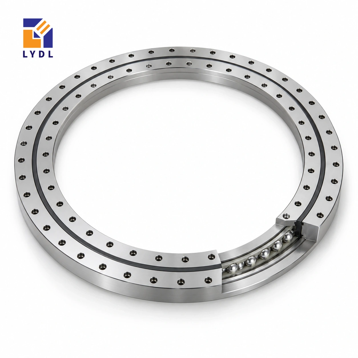
VU130225 is a gearless four-point contact ball slewing reference with a 200 mm bore and 290 mm outside diameter. Its 24 mm overall height makes it a distinct shallow package within the requested VU models, with a mounting arrangement that needs particular attention.
VU130225: current LYDL nominal table. Confirm the supplied configuration and limits by drawing.
VU specification tables · Family technical reference
| Bore (mm) | Outside (mm) | Height H (mm) | Mass ≈ (kg) |
|---|---|---|---|
| 200 | 290 | 24 | 5.4 |
| Outer PCD La (mm) | Outer holes na | Secondary h (mm) |
|---|---|---|
| 270 | 6 | 24 |
The current website lists a 270 mm outer fixing circle and six outer positions, but does not provide a conventional inner fixing circle or a dB value in this row. Missing entries should not be converted to zero or copied from another VU model. Obtain the exact inner connection and centring details before designing the rotating plate. A large clear opening and shallow height do not fully describe how the machine parts are attached.
Review the complete section, including any thread, locating shoulder or alternative inner attachment shown on the accepted drawing. Confirm screw access without presuming that the outer six-hole pattern repeats on the inside.
Ask for a section showing the complete inner connection and identify which feature locates the mating part. If threads or special shoulders appear on the offered drawing, request their full specification there instead of adding an assumed conventional bolt pattern. Decide how the rotating plate is installed and removed without straining the shallow ring. Record the actual working-level datum and any adapter thickness.
This is the basis for machining; the missing entries in a public series row are a reason to obtain the drawing, not an instruction to improvise an attachment.
Read VU130225 as a four-point contact ball reference with 200 mm bore, 290 mm outside diameter and 24 mm overall H. The separate h entry is 24 mm; use its labelled drawing feature rather than assuming it describes the whole assembly. The approximate listed mass is 5.4 kg and supports component handling information, not a payload rating. La = 270 mm locates the outer fixing circle; it is not the outside diameter. A connection also needs its hole form, screw engagement and locating features. Compare those items with the actual machine drawing before releasing mating parts. Values absent from the website row remain unresolved rather than becoming zero. The nominal table helps identify the intended geometry, while the agreed supply drawing defines the purchased execution.
The nominal envelope is 200 mm bore by 290 mm outside diameter with 24 mm overall H. The website row also identifies six outer positions on a 270 mm circle. It does not provide a conventional complete inner pattern or the hole diameter needed to design that interface. Missing entries remain unresolved; they must not be interpreted as zero or copied from another VU size.
Send the intended upper and lower mating parts with the enquiry. Label the features that locate and secure each side, and ask for the offered section and connection details. A useful dimensional study can start from the published envelope, while the inner attachment must be settled before machining or purchase.
A compact manual or driven fixture may have a strict working-height limit. Place the 24 mm ring in the complete section, including adapters, screw seats and the fixture plate. Identify the actual mounting planes. If an adapter is needed to resolve the connection, its thickness and locating features become part of that stack.
Show how tools reach the outer six-position pattern and the proposed inner attachment. Check whether the fixture can be centred and removed without disturbing unrelated equipment. A shallow nominal ring does not automatically produce a shallow, serviceable machine. The unresolved interface should be recorded on the drawing as a question for the offer, rather than hidden by a generic plate illustration.
VU130225 belongs to the four-point contact ball group and is ungeared. Neither the contact principle nor the small listed mass assigns a precision grade or permissible payload. Describe the part, fixture and force locations, including manual loading or clamping at an offset. State any requirement for rocking movement or angular position at a named working datum.
For powered motion, identify angular travel, acceleration and the moving mass distribution. For manual movement, explain how force is applied and what holds the fixture during processing. Request assessment of the offered execution against those conditions. A claimed general capacity without the supplied clearance, connection and support information would not answer the actual equipment question.
Because this ring has no integral gear, show the chosen transmission and its support. A belt, friction wheel or linkage applies force at its own location. Include tension, contact or bracket reactions relevant to the assembly instead of reporting only the desired output torque. Confirm how the drive is adjusted and removed.
Keep the drive clear of the unresolved connection until the offered geometry is known. A bracket designed too early can block a necessary fastener or locating feature. Describe a separate holding arrangement if one is used during dwell. This gives the supplier a coherent layout to review while preserving the distinction between known nominal dimensions and features awaiting confirmation.
Agree the supplied identity and accepted connection drawing before defining receiving inspection. Specify which features are checked and under what support condition. Separately define any observation of the completed fixture. Keep the adapter and transmission revisions with the baseline result so later comparisons use the same arrangement.
Discuss the actual contamination, cleaning and storage interval when selecting the offered protection. Plan packing around the approximately 5.4 kg component without loose hardware contacting machined surfaces. The generic photograph cannot verify the missing connection or certify a test of this model. Retain the confirmed drawing with future spare enquiries so the unresolved public row is not repeatedly used as a manufacturing specification.
VU140179 has a 124.5 mm bore and 35 mm H, while VU200220 has a 138 mm bore and 46 mm H. The present 200 mm bore and 24 mm height provide a very different dimensional option despite the smaller number embedded in its designation. Reading model numbers as a monotonic sequence of openings or heights would be misleading.
The six-position outer connection and missing conventional inner interface make this row especially dependent on a complete drawing enquiry. A nearby VU reference cannot supply the absent features by analogy. Compare the actual machine attachment first, including whether an adapter is acceptable within the height allowance.
If an existing component motivates the request, show its identifiable boundaries and measured mating features, with a section through the connection. Record what was measured and what remains unknown. This allows LYDL to identify a specific offered execution. Keep that resulting revision for repeat supply so the public envelope is used as a search aid rather than mistaken for a complete manufacturing specification.
A low-profile packaging changeover platform is an illustrative layout. Evaluate product-feed clearance and the effects of operator forces applied at the platform edge during adjustment.

Agree which attachment features need dimensional acceptance and name them on the inspection plan. Use a stable flat support during transport, with protection around the thin axial package.

It has a 24 mm height and a listed six-position outer connection; the conventional inner fixing circle and dB entries are not supplied.
No. They are unspecified in the row. The accepted drawing must define the actual attachment details.
The current LYDL reference is 200 × 290 × 24 mm, with approximate mass 5.4 kg.
Do not assume that arrangement. Confirm the supplied inner connection and centring design before machining a mating plate.
Include forces applied at handles or the table edge and their lever arms, as these can differ from normal product-transport loads.
Compare roller principles through XU series and XSU range.
For VU130225, request the complete inner-connection drawing before finalising either mating component.