

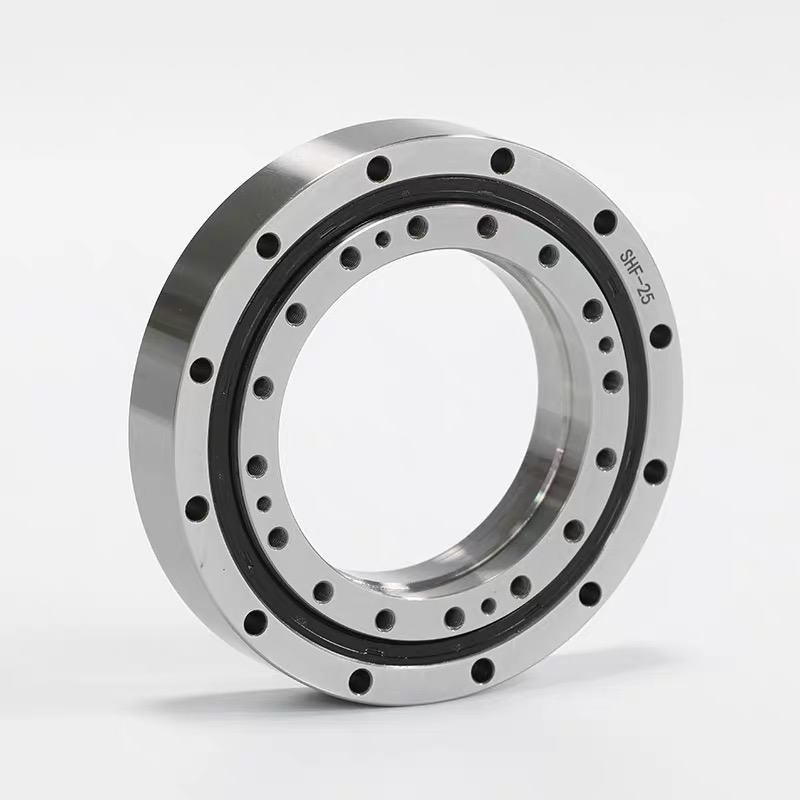
SHF-14 / SHG-14 cross roller bearing dimensions in the LYDL reference are d = 38 mm, D = 70 mm and H = 15.2 mm. The separate d3 reference is 36 mm. When reviewing a compact hollow-shaft assembly, check not only the cables in service but also the connectors that must pass through during installation. This page focuses on that route and the bearing interfaces around it.
Compare this model with the SHF / SHG selection guide before confirming the interface.
Draw the complete centre passage through the joint, including adjacent shafts, flanges, seals and supports. The bearing reference diameter does not establish the available opening through the finished reducer. List each cable or hose and its connector, then identify how it will be installed. A connector may require more space than the cable it serves, especially when an angled approach is unavoidable.
Check whether components are routed before or after the output support is fitted. Record bend requirements, restraints and the relative movement of the connected parts. The design should explain how services are protected throughout travel. A hollow bearing opening does not by itself prevent twisting, rubbing or a connector becoming trapped during assembly.
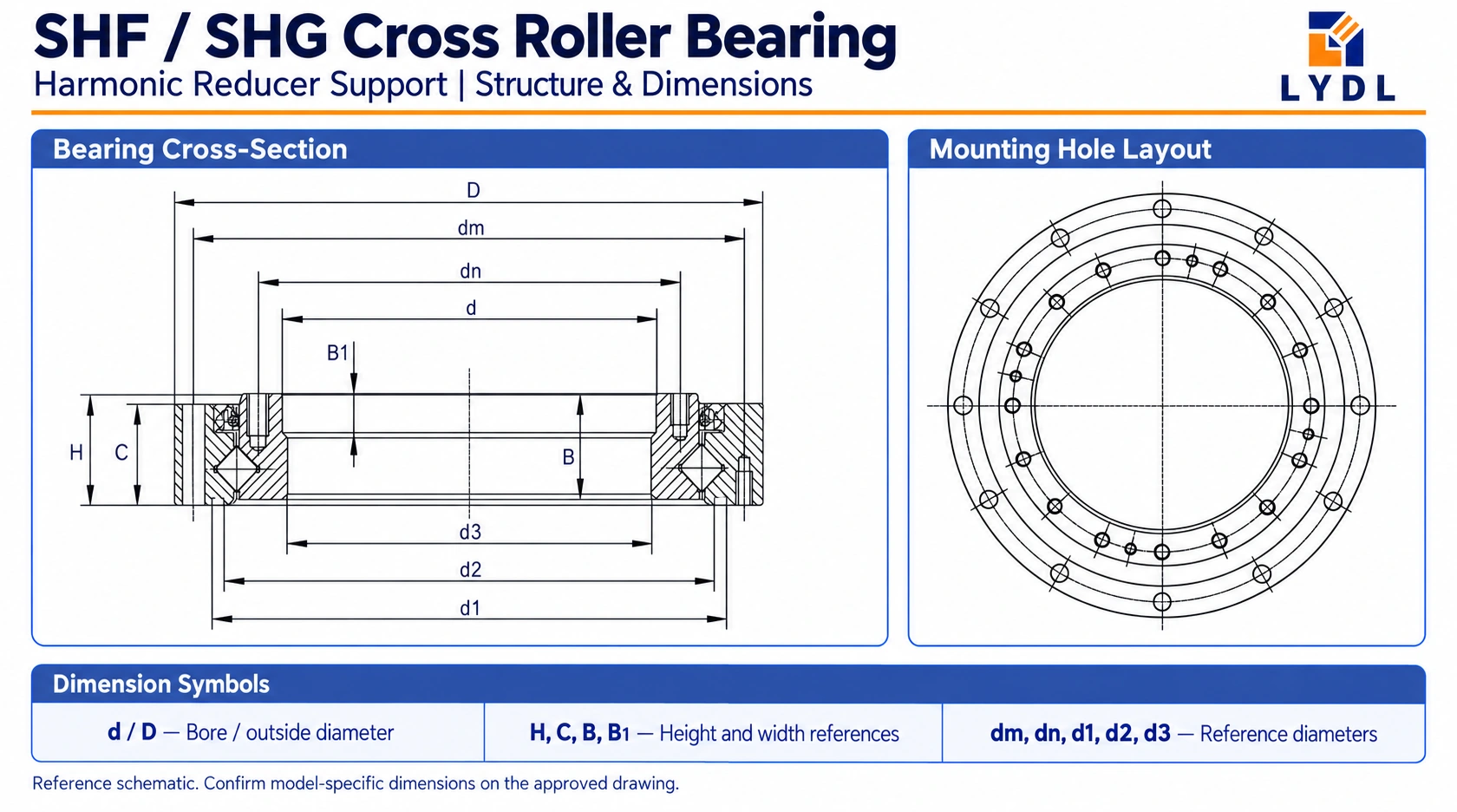
The structure diagram uses d for the 38 mm bore reference and d3 for a different 36 mm diameter. Assign each to its location in the section before using it as a clearance value. D = 70 mm describes the outside diameter, while H = 15.2 mm is the overall axial reference. C = 14.2 mm, B = 13.7 mm and B1 = 5 mm identify additional axial features.
Secondary diameters d1 = 57 mm and d2 = 53 mm help locate other interfaces. dm = 64 mm identifies the published outer mounting circle. The numerical table does not specify a complete hole pattern or thread depth; request those details on the model drawing. The SHF / SHG bearing category groups this family without treating an illustrated plan view as the confirmed pattern for every part.
| Reference feature | Value |
|---|---|
| d (mm) | 38 |
| d3 (mm) | 36 |
| D (mm) | 70 |
| H (mm) | 15.2 |
| C (mm) | 14.2 |
| B (mm) | 13.7 |
| B1 (mm) | 5 |
| d1 (mm) | 57 |
| d2 (mm) | 53 |
| dm (mm) | 64 |
Dimensions: existing LYDL selection reference. The approved model drawing defines tolerances, variant mapping and supplied interfaces.
A routing mock-up should include the largest connector, its protective boot and the tool access needed to install it. Consider the order in which the housing, bearing, driven flange and service harness are assembled. If the connector cannot pass an internal step, confirm whether an approved assembly sequence or a different connector arrangement resolves the issue.
Do not enlarge a locating feature merely to obtain routing clearance without reviewing the component design. Keep the service-envelope requirement separate from bearing seats and registers. Mark the restrictive feature in the assembly section and state the needed installation clearance. This gives the drawing review a concrete question rather than a general request for a larger hollow bore.
The output bearing reacts mechanical forces from the driven mechanism. Describe the attached bracket or tool, its offset and the movements of the joint. Cable restraints can also introduce forces, so include their effect where relevant. A clear service passage does not establish sufficient radial, axial or moment capacity for the working load.
The original SHF and SHG unit descriptions identify hollow-shaft gear units with output support; their transmission ratings belong to those assemblies. The supplied bearing needs confirmed performance for its own configuration. This page deliberately leaves unavailable component ratings unspecified. Review the LYDL cross roller bearing range if the application needs another support construction, rather than choosing a different family solely for its apparent opening.
Identify the required runout at the driven flange and the point where movement affects the tool. Agree the clearance or preload, running behaviour, sealing and lubrication arrangement. State whether measurements are made before mounting or with the routed services fitted. A harness can change the mechanism's resistance over travel even when the bearing condition is unchanged.
Prepare clean seating faces and confirm the registers before tightening the agreed fasteners. Check movement across the planned travel, watching both flange behaviour and cable clearance. Do not equate a complete gearbox accuracy value with the bearing's precision class. If a routing issue appears after clamping, investigate the harness path and adjacent parts as well as the mechanical support.
Industrial robotics may use this position in a compact joint with electrical or pneumatic services passing through the centre. Machine-tool positioning may involve an orienting attachment needing a protected signal route. Semiconductor handling can involve a small articulated head with vacuum or sensor connections. Medical robotics may involve a positioning joint with application-specific cable and device validation.
The illustration is a guide to possible equipment contexts, not a photograph of a qualified size-14 installation. Each route, cleanliness requirement and permissible load must be checked for the actual assembly. A similar application name does not establish an identical connector or bearing interface.

Agree inspection of the bore steps, seating faces and model-specific mounting features. Include specified rotational checks and identification of the drawing revision. Retain the reviewed passage section with the order documents so the bearing and adjacent parts can be recognised during later maintenance. The LYDL company and manufacturing information offers company information alongside this technical review.
Protect the faces and central features during packing. Keep loose hardware away from the machined surfaces and discuss individual wrapping or restraint for the transport route. Use a real inspection and packaging photograph when available, or identify a representative image accurately. It cannot replace the component report or certify a complete harness installation.

The bearing d value is only one dimension in the route. Check the smallest assembled opening, connector envelope and installation approach. Include boots, adjacent steps and the order of assembly before confirming a connector can pass.
It identifies a separate diameter feature in the reference section. Determine which surface and axial position it describes. Use the complete assembly drawing to establish clearance rather than substituting one diameter symbol for another.
The family plan view is illustrative. The size-14 numerical table supplies dm but not the full fixing specification. Request hole quantity, thread or through-hole detail, orientation and depth on the approved model drawing.
Cable bends and restraints may add resistance or create contact at certain positions. Inspect the full travel with the intended routing arrangement, while keeping bearing-related checks distinguishable from harness behaviour. Record the mounting and test conditions.
Provide an assembly section, connector dimensions and proposed installation sequence. Identify the limiting step or opening and required service route. Add the complete reducer designation so the interface review addresses the actual configuration.
Submit the size-14 passage section and connector envelope through LYDL technical enquiry. Include the bearing interfaces, load arrangement, quantity and travel requirements. LYDL can review the component drawing alongside the routing information before a supply specification is agreed.
LYDL supplies its own bearings. Referenced brand names identify comparison families; agreed drawings and order specifications define supplied performance.