

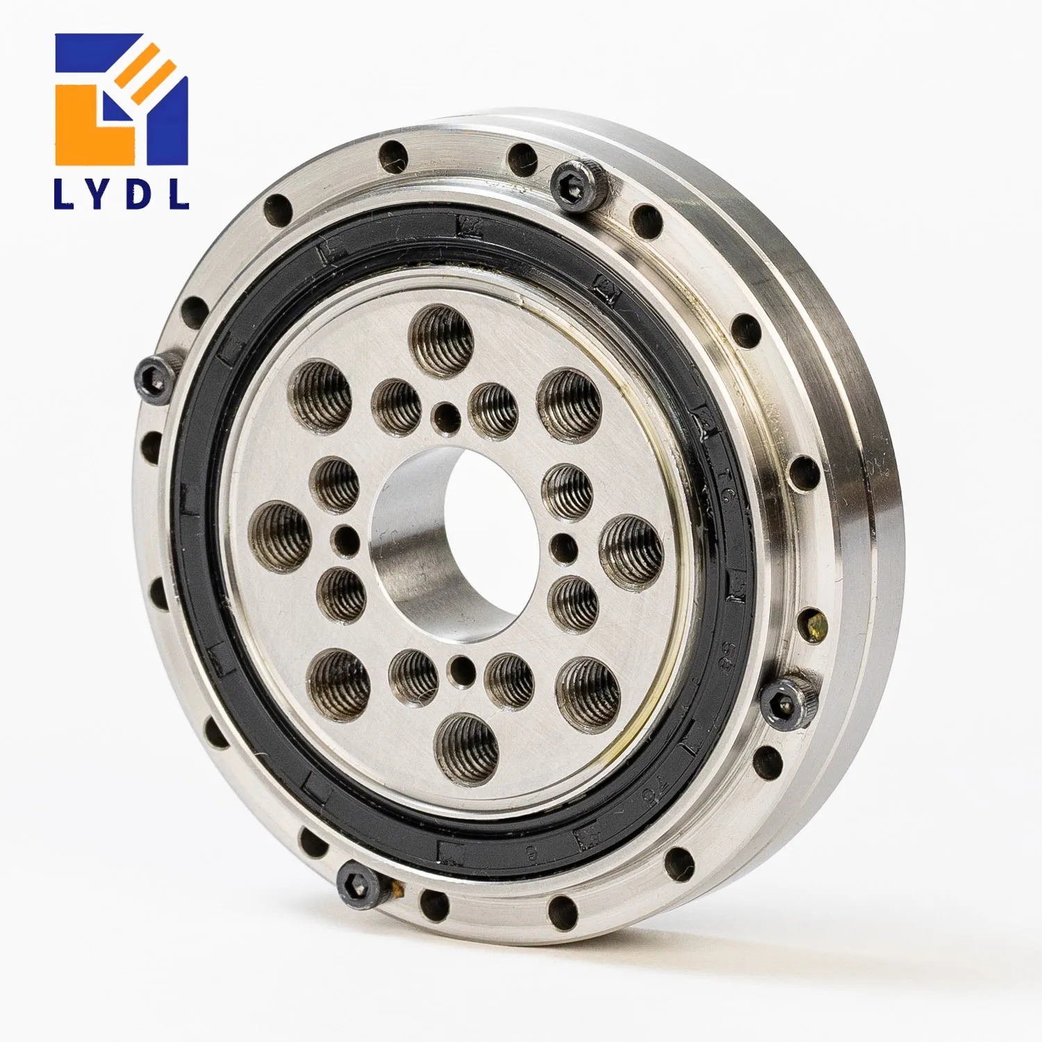
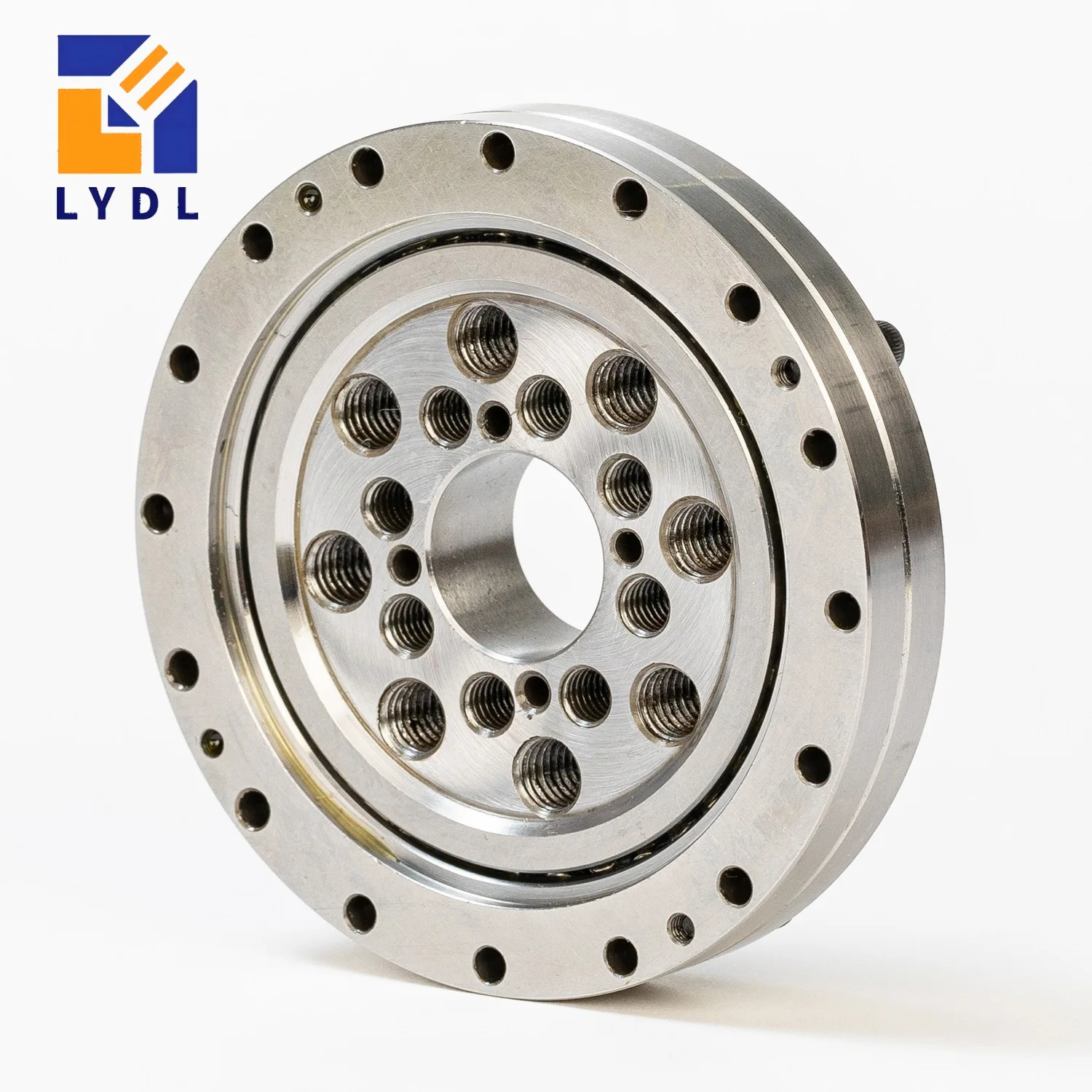
CSG-50 / CSF-50 cross roller bearing selection uses a LYDL reference outside diameter of 157 mm and overall height of 31 mm, with bore alternatives of 40 and 32 mm. For a fixture-positioning assembly, the main concern is keeping the locating faces, fastening arrangement and operating loads consistent through tool changes. This page sets out the size-50 interfaces and the information needed for a controlled enquiry.
Compare this model with the CSG / CSF selection guide before confirming the interface.
List the fixtures and workpieces expected on the driven flange. Identify the mass distribution and working radius for each, including adapters and clamps. A lighter fixture can still produce a demanding moment if it extends farther from the support. Describe the process force direction and whether it is reacted through the bearing or a separate machine structure.
Review acceleration and stopping with the actual inertia of each arrangement. Do not use one nominal payload to describe every changeover configuration. The replacement or new bearing specification should cover the agreed operating envelope, with severe conditions assessed by the machine designer. Keep the drive-torque requirement distinct from the external support loads when comparing original gear-unit data.
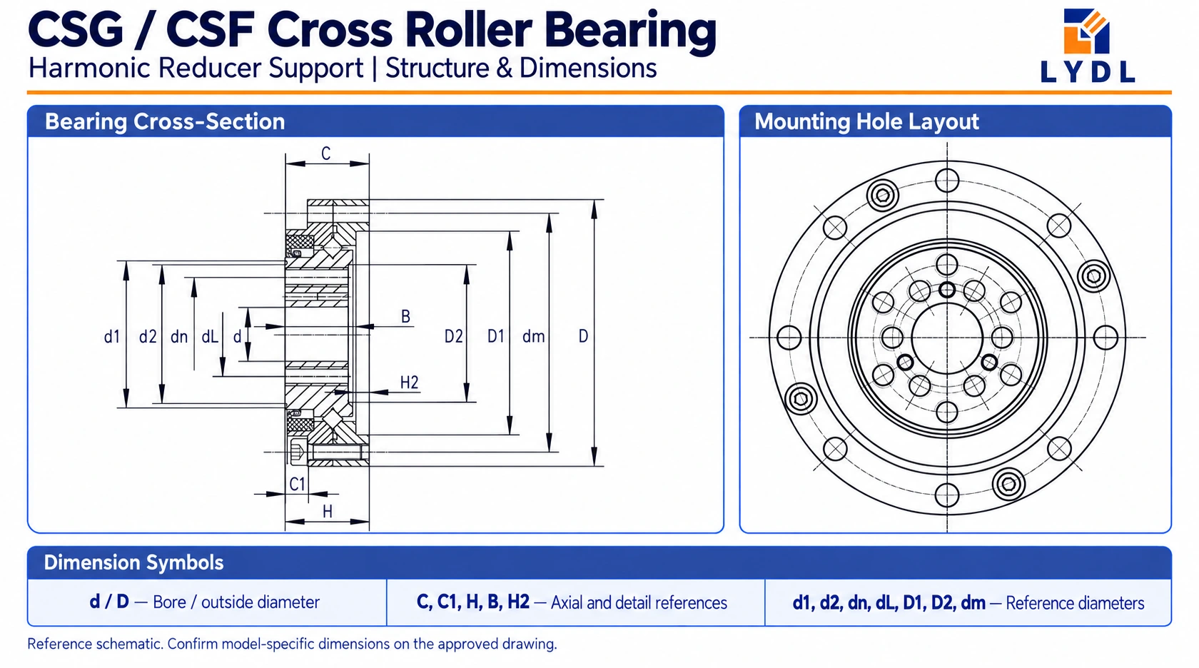
The d = 40(32) mm entry refers to alternative source-table configurations. Confirm the matching variant before machining a shaft or adapter. H = 31 mm, C = 30 mm, B = 28 mm and H2 = 3 mm identify different axial features. Their drawing locations determine the flange stack-up; they are not independent substitutes for the overall bearing height.
D1 = 131.6 mm, D2 = 98 mm, d1 = 108 mm and d2 = 102.6 mm identify additional diameter references. Use the section to associate them with the locating faces and required clearances. The CSG / CSF bearing category provides a path to other sizes if the available envelope changes. It does not remove the need to verify this model's bore and mating surfaces.
| Reference feature | Value |
|---|---|
| d (mm) | 40(32) |
| D (mm) | 157 |
| H (mm) | 31 |
| C (mm) | 30 |
| B (mm) | 28 |
| H2 (mm) | 3 |
| D1 (mm) | 131.6 |
| D2 (mm) | 98 |
| d1 (mm) | 108 |
| d2 (mm) | 102.6 |
| Outer PCD dm (mm) | 147 |
| Outer fixing holes | 16-Φ5.5 |
| Inner PCD dn (mm) | 84 |
| Inner fixing holes | 8-M14 |
| Additional PCD dL (mm) | 60 |
| Additional fixing holes | 8-M14 |
Dimensions: existing LYDL selection reference. The approved model drawing defines tolerances, variant mapping and supplied interfaces.
Sixteen 5.5 mm outer holes are listed at dm = 147 mm. The inner circle dn = 84 mm carries eight M14 threads, and the additional dL = 60 mm entry also lists eight M14 threads. Determine the mating part for each circle. Equal thread designations do not establish the same register, engagement depth or direction of assembly.
Check how the fixture can be attached and removed without damaging the bearing seat. Allow access for the specified hardware and inspect clearance behind each threaded connection. Confirm the bolt condition and assembly instructions for repeated changes. The hole table is an identification aid; tightening torque and bolt performance require the actual joint specification rather than an assumption from nominal thread size.
A repeatable fixture interface depends on clean, undamaged locating surfaces. Plan a procedure that prevents chips, raised edges or loose hardware from becoming trapped during attachment. Use the designated register to locate the fixture and verify full seating before tightening. Record any features that need protection when the fixture is removed.
If an adapter is added, assess its contact area and stiffness with the complete support. A change in fixture height can change the force offset and workpiece position. Do not attribute every positioning error to bearing runout without checking the adapter and mating faces. Compare the LYDL cross roller bearing range when redesigning the mechanism, especially if another bearing construction would require different locating or fastening interfaces.
| Reference feature | Value |
|---|---|
| Basic dynamic load C (kN) | 34.8 |
| Basic static load C0 (kN) | 60.2 |
| Catalogue moment Mc (Nm) | 759 |
Harmonic Drive catalogue, printed page 33, Table 30. Source load units ×10² N converted to kN. Confirm configuration and rated conditions before calculation.
Specify the measurements needed at the working fixture: runout, allowable movement and running resistance under defined conditions. Identify whether those checks occur at component receipt or on the completed machine. Include the tool or workpiece arrangement used in a loaded assessment. Bearing accuracy and whole-machine positioning performance should remain separate acceptance topics.
The original 2UH load figures below are retained with their source and assembly identity. They are not a confirmed LYDL component rating. Request the supplied configuration's dynamic, static and moment data, plus the appropriate operating assumptions. State movement, lubrication access, environment and required life so the review can address the actual fixture duty rather than only its maximum diameter.
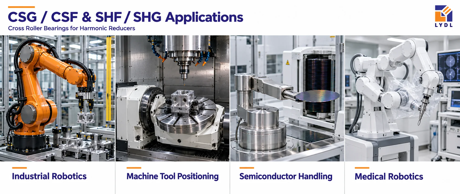
An industrial robot may use similar support behind a tool or process-fixture flange. Machine-tool positioning may use it in an orienting attachment with explicitly defined machining or clamping forces. Semiconductor handling can involve a transfer mechanism carrying changeable tooling, with separate environmental qualification. Medical robotics may use comparable support in controlled positioning equipment, subject to its own validation.
The graphic covers application fields. It is not a record of approved size-50 installations, nor a payload specification. Drawings, load conditions and supplied performance data establish suitability for a particular mechanism.
Make the critical locating diameters and seating faces explicit in the inspection plan. Confirm the chosen bore configuration, mounting details and agreed rotational checks against the approved revision. The report should identify the supplied part so maintenance personnel can relate it to the fixture design. Review LYDL company and manufacturing information as part of the supplier information package.
Specify wrapping and restraint that protect both faces and prevent contact with spare bolts or other components. Discuss storage needs if the bearing will remain as a maintenance spare. The inspection and packing illustration should match the described method or carry a representative label; it should not imply an unagreed load test or model-specific certification.

Provide each relevant mass distribution, offset and process-force case. Include the adapter and clamps, not just the workpiece. Define the intended operating envelope so the bearing review covers meaningful changes in inertia and support loading.
They are separate interfaces in the reference table. Their roles, locating surfaces and mating parts require the model drawing. Do not assume that identical thread size or hole quantity makes either circle suitable for the same fixture.
Thread size does not define the complete bolted joint. Bolt grade, engagement, lubrication, mating materials and the assembly design matter. Follow the approved installation specification and verify access and clearance for the intended fasteners.
Check the designated registers and contact faces for damage or trapped material. Confirm seating, hardware condition and the agreed mounted rotational checks. Changes at the fixture interface can affect positioning even when the bearing itself has not been replaced.
A bearing reference and a complete gear unit are different items. Confirm mass for the actual supplied component if handling or inertia depends on it. Do not transfer a mass value between assemblies solely because their family and size labels match.
Use LYDL technical enquiry to send the size-50 flange drawing, bore variant and fixture-changeover load cases. Include quantity, acceptance measurements and protection requirements. LYDL can review the component specification with the actual locating and fastening arrangement in view.
LYDL supplies its own bearings. Referenced brand names identify comparison families; agreed drawings and order specifications define supplied performance.