

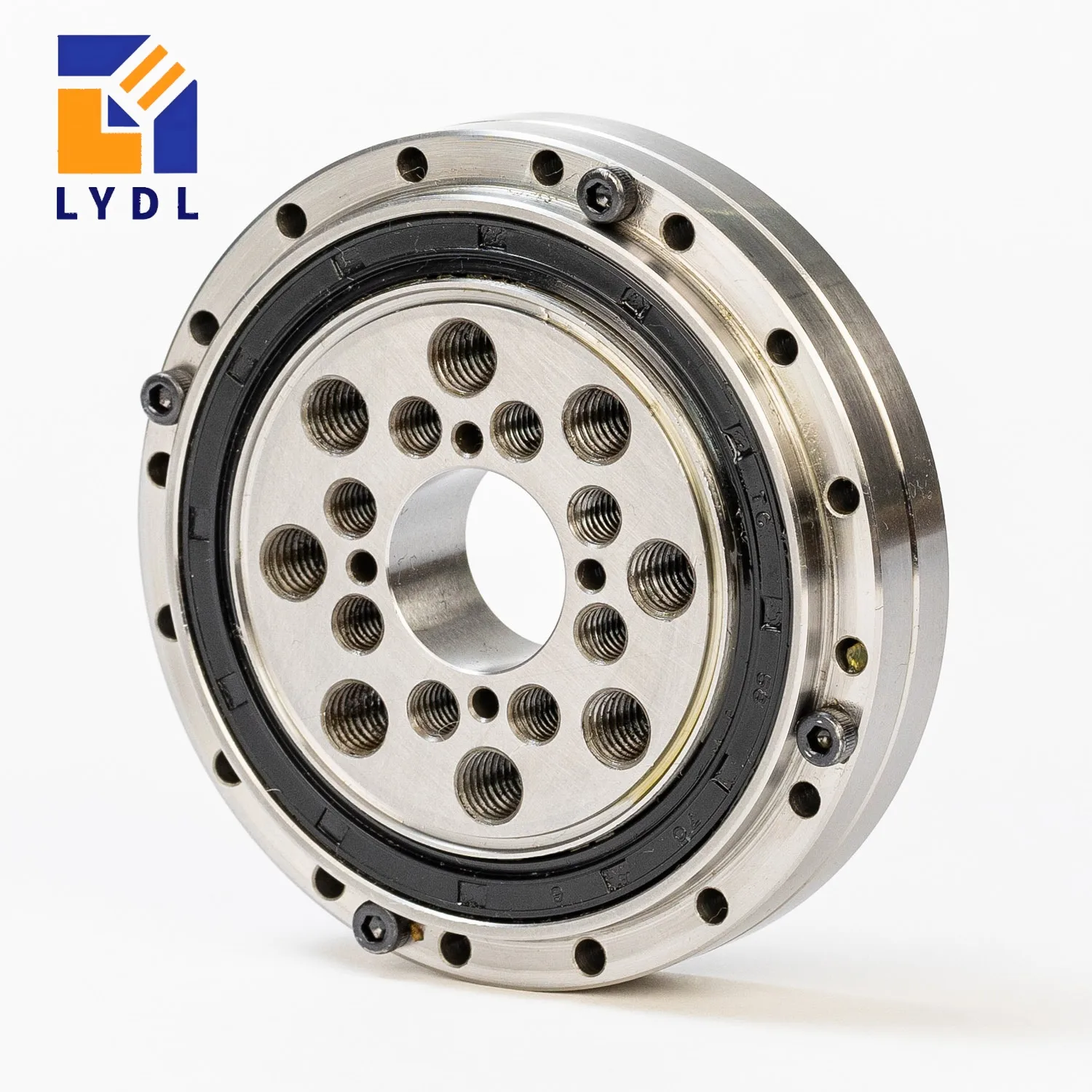
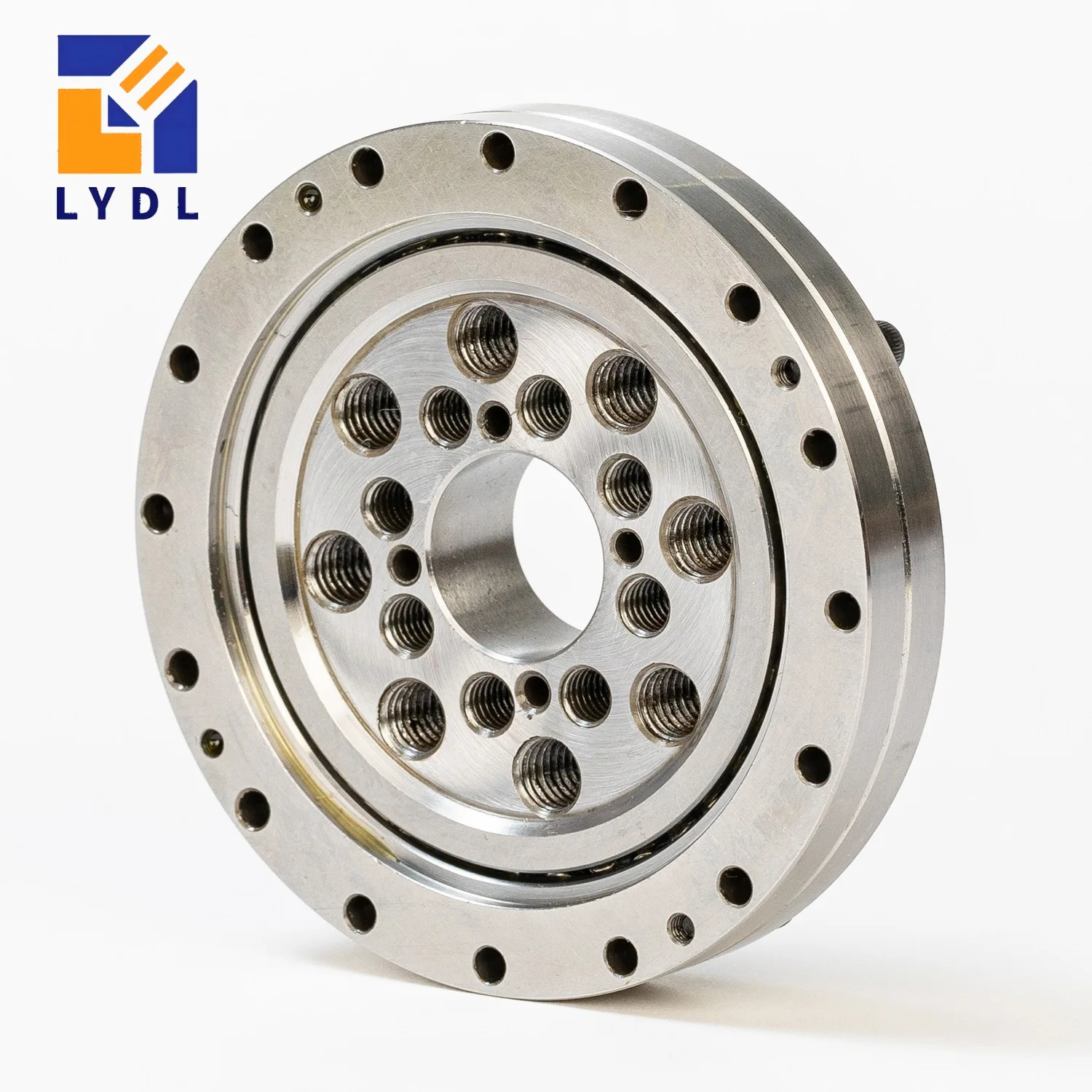
CSG-40 / CSF-40 cross roller bearing review starts with the LYDL reference of 126 mm outside diameter and 24 mm overall height. Its bore entry is 32(24) mm, so a replacement order must identify the matching configuration before choosing a part. The emphasis here is on controlled variant identification, seating surfaces and a reliable maintenance record.
Compare this model with the CSG / CSF selection guide before confirming the interface.
Record the complete reducer code, any special suffix and the bearing's orientation while it is still in the assembly. Photograph the locating seat, both flange faces and the fasteners that secure each connection. Where maintenance history exists, check whether an earlier repair modified the housing or tool adapter. An old component may show the result of such a modification rather than the intended standard interface.
Separate measured information from assumptions. Mark uncertain dimensions and request the controlled drawing associated with the unit. The 32(24) mm reference contains alternative bore entries, not a continuous tolerance band. Its relationship to the original configuration must be confirmed; the existence of both values does not authorise substituting one for the other.
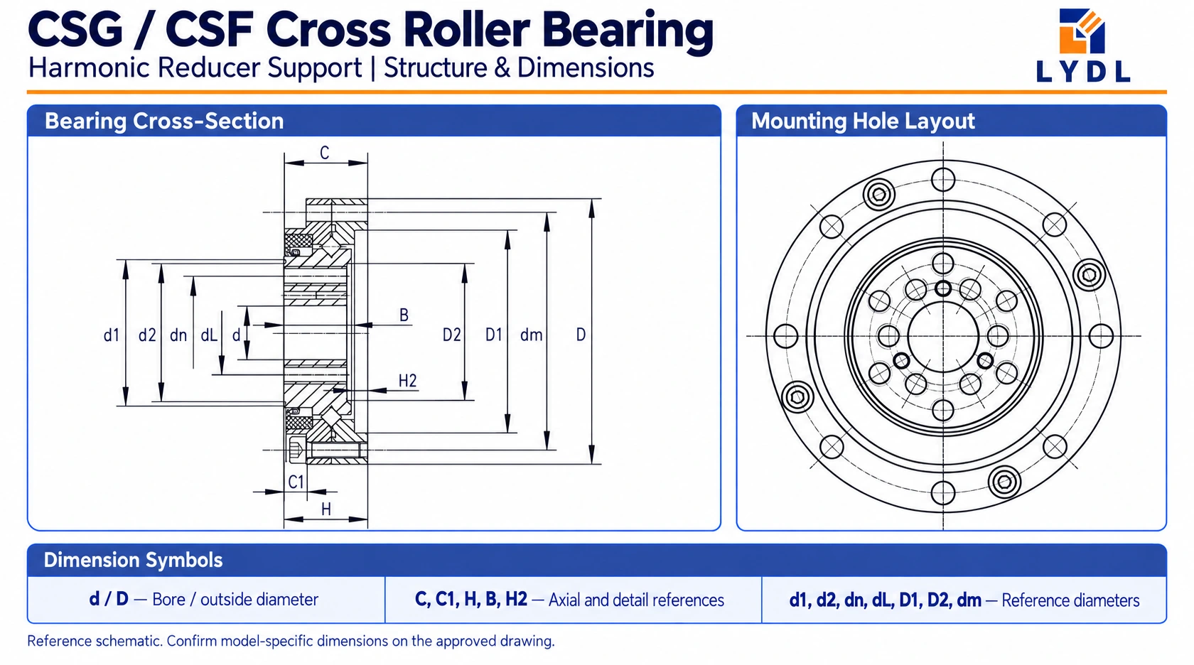
Read the bearing and neighbouring housing in one assembly section. H = 24 mm is the overall axial reference; C = 22.5 mm, B = 21.5 mm and H2 = 2.5 mm identify further details. Check where each shoulder contacts the ring and where clearance is required. The useful comparison includes the position of the driven flange after mounting, not merely the loose component's height.
The diameter references D1 = 105 mm, D2 = 86 mm, d1 = 86 mm and d2 = 81.2 mm should be assigned to their actual surfaces. Similar numerical values can describe different locations. Preserve letter case and the drawing symbols when sending a measurement report. The CSG / CSF bearing category helps organise the available family references, while the approved section defines the particular part.
| Reference feature | Value |
|---|---|
| d (mm) | 32(24) |
| D (mm) | 126 |
| H (mm) | 24 |
| C (mm) | 22.5 |
| B (mm) | 21.5 |
| H2 (mm) | 2.5 |
| D1 (mm) | 105 |
| D2 (mm) | 86 |
| d1 (mm) | 86 |
| d2 (mm) | 81.2 |
| Outer PCD dm (mm) | 117 |
| Outer fixing holes | 20-Φ5 |
| Inner PCD dn (mm) | 68 |
| Inner fixing holes | 8-M10 |
| Additional PCD dL (mm) | 50 |
| Additional fixing holes | 8-M10 |
Dimensions: existing LYDL selection reference. The approved model drawing defines tolerances, variant mapping and supplied interfaces.
The published outer reference has twenty 5 mm holes at dm = 117 mm. The inner interface lists eight M10 holes on dn = 68 mm; the additional eight-M10 interface is on dL = 50 mm. Confirm hole orientation, access, depth and the components secured at these connections. The generic structure image explains the layout but does not certify a model's complete fastening details.
Check the condition of the mating threads during replacement. Damaged threads, incorrect bolt lengths or missing contact surfaces cannot be resolved by fitting a new bearing alone. Define any repair or redesigned adapter before approving the component. Avoid using the surrounding fasteners to force an incompatible register or axial step into the assembly.
Describe why replacement is required: a change in running resistance, visible damage, measured runout or movement under load. Include the test conditions and location of the observation. Those symptoms may involve the bearing, its installation or the attached structure. A useful review distinguishes the component evidence from the mechanism's overall behaviour.
Reconfirm current loads and motion even when the replacement seems identical. Changes in tooling, force offset, cycling or lubrication access can affect the requirement. The original 2UH rating reference below remains attached to its specified assembly. Ask for the supplied LYDL configuration and data rather than importing gearbox torque or complete-unit accuracy as bearing attributes.
| Reference feature | Value |
|---|---|
| Basic dynamic load C (kN) | 21.3 |
| Basic static load C0 (kN) | 36.5 |
| Catalogue moment Mc (Nm) | 450 |
Harmonic Drive catalogue, printed page 33, Table 30. Source load units ×10² N converted to kN. Confirm configuration and rated conditions before calculation.
Define the critical seats and locating surfaces on the drawing, then agree the rotational checks needed for the order. State whether runout is measured before mounting or at the installed flange, and identify the relevant radius. Clearance or preload, running torque and seal arrangement should be part of the agreed configuration. Generic precision labels are insufficient if they do not establish the acceptance conditions.
After installation, inspect rotation with the mating flange and protective components fitted. Record the result using the same procedure as the baseline assembly. When a different support construction is being considered, compare the LYDL cross roller bearing range to understand the interface implications. A dimensional resemblance is not enough to approve a change to the machine's support arrangement.
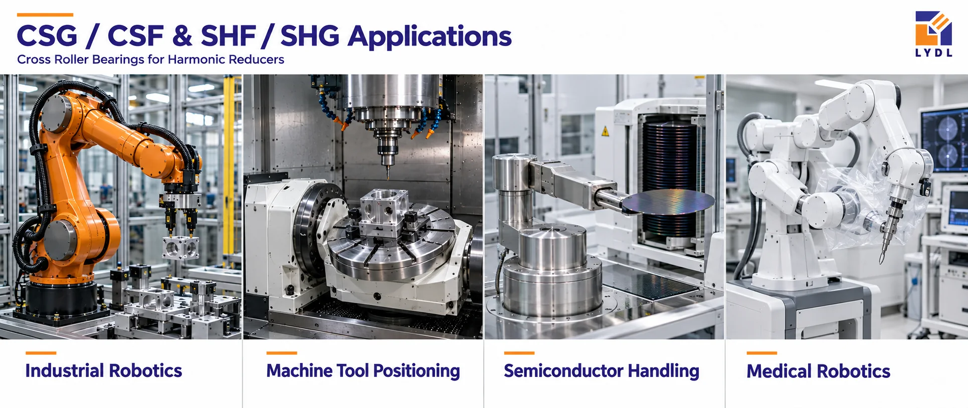
Industrial robotics may use this reference in a driven joint whose tooling and maintenance history should be documented. Machine-tool positioning may involve an orienting axis with measured flange runout. Semiconductor handling can involve a larger transfer mechanism requiring stable movement and environmental review. Medical robotics may use similar mechanical support in a positioning axis, subject to device-specific assessment.
The application graphic illustrates sectors rather than specific installed parts. It cannot establish the cause of a maintenance issue or prove compatibility. Select the replacement from the actual unit identification, dimensions and working conditions.
Ask the inspection report to identify the chosen bore variant and the approved drawing revision. Relate each measured characteristic to its symbol or functional surface. Where a maintenance team will stock the part, include sufficient identification to prevent the alternative bore configuration being mistaken for it. The LYDL company and manufacturing information provides supplier context alongside these technical documents.
Discuss face protection, restraint and corrosion precautions for the delivery route and expected storage. Packaging should prevent contact with unrelated hardware and make removal straightforward. A representative image can explain the method, but the agreed packing instructions and inspection report remain the relevant records for the actual order.

It denotes alternative reference entries in the source table. Determine the configuration and drawing associated with each value. Do not interpret the notation as an allowable bore range or as permission to choose either diameter for the same assembly.
It helps identify how the seats and fastening interfaces relate to the fixed and driven parts. Photographs taken before removal can preserve details that a loose bearing does not explain. Verify the arrangement against the controlled assembly drawing.
Identify the damage and proposed repair separately. The replacement bearing must match an approved interface, while the mating structure must provide sound fastening and seating. A new bearing cannot compensate for an undefined thread or register repair.
Record the measurement surface, radius, mounting state and applied load, together with the observed value. A consistent method supports comparison before and after replacement. An unexplained total reading may combine several sources of movement.
Check the bore variant, registers, axial details and fixing interfaces before acceptance. Similar appearance does not establish the exact configuration. Use the part identification and agreed inspection criteria to distinguish a suitable spare from another size-40 reference.
Send the removed-part photographs, bore variant and maintenance observations via LYDL technical enquiry. Include the controlled housing section if available, current duty and desired quantity. LYDL can review a size-40 replacement with the configuration and acceptance conditions made explicit.
LYDL supplies its own bearings. Referenced brand names identify comparison families; agreed drawings and order specifications define supplied performance.