

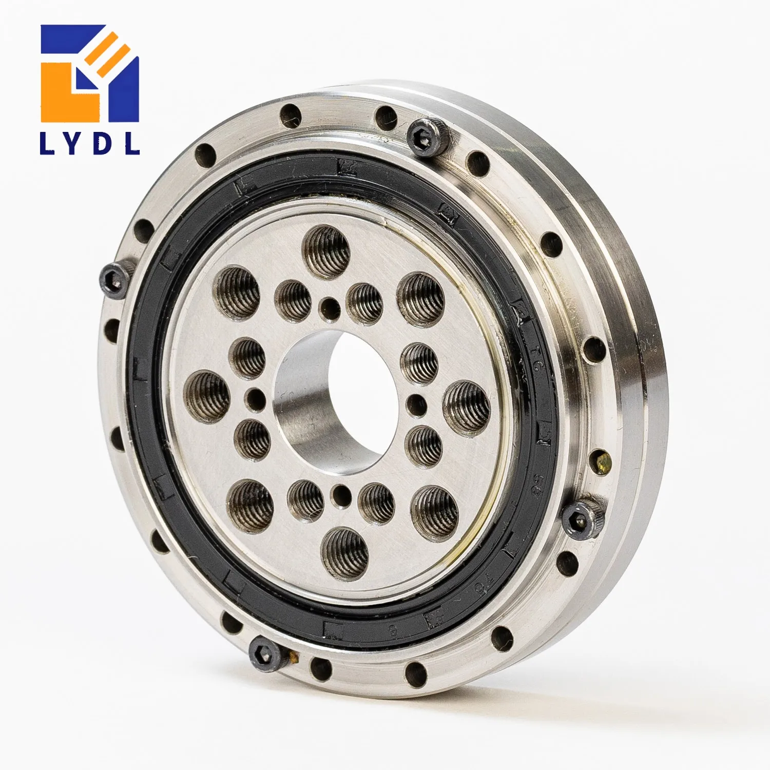
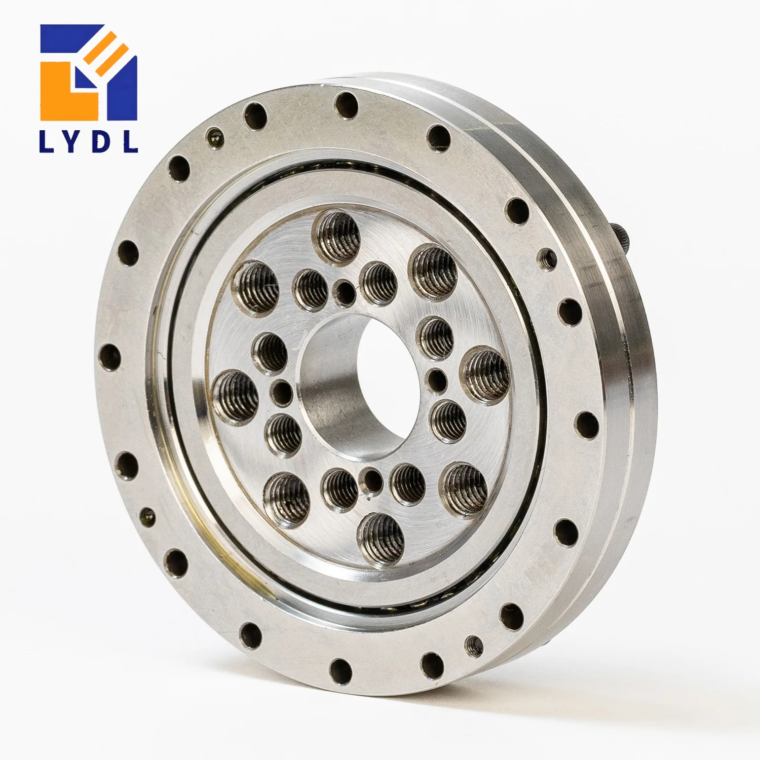
CSG-17 / CSF-17 cross roller bearing references describe a 10 mm bore, 62 mm outside diameter and 16.5 mm overall height in the LYDL selection table. For a compact actuator or laboratory positioning mechanism, this page concentrates on flange access, repeatable movement and a clear acceptance specification. Size 17 identifies the reference family; it does not mean a 17 mm bearing bore.
Compare this model with the CSG / CSF selection guide before confirming the interface.
Begin by locating the bearing relative to the fixed housing and the moving output flange. A complete actuator may contain several bearing positions with different functions. The crossed roller output support carries external forces from the attached mechanism; it should not be confused with the flexible wave-generator bearing inside a strain-wave transmission. Record the complete original unit designation before requesting a replacement.
Check the revision and preserve mounting photographs. Use the CSG / CSF bearing category for navigation; the assembly drawing confirms applicability.
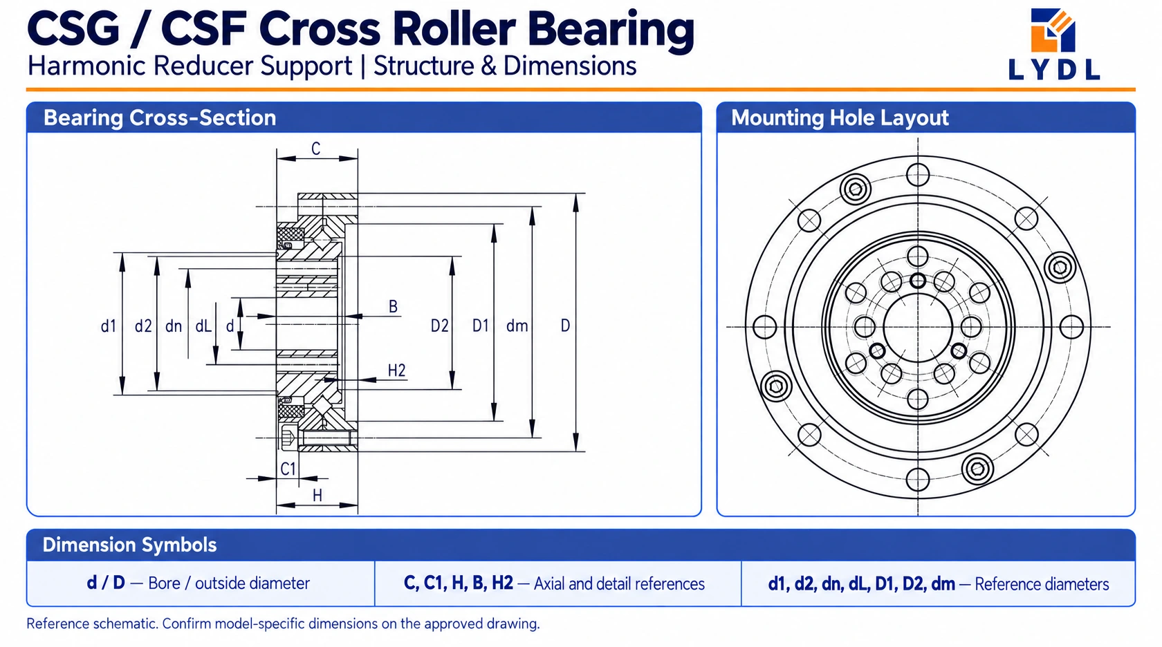
Use d for the 10 mm bore and D for the 62 mm outer diameter. H is the overall 16.5 mm axial reference; C = 16 mm, B = 13.5 mm and H2 = 2.5 mm identify other features in the drawing. Do not treat every axial symbol as a second specification for the same overall width. The section and its numerical labels need to be read together.
The outer mounting reference has ten 3.5 mm holes at dm = 56 mm. The inner mounting entry is six M5 holes at dn = 27 mm, with an additional six-M5 reference on dL = 19 mm. Check the function of each interface, threaded depth and orientation before choosing bolts. Distinguish the locating registers from the bolt circles; fastening and centring perform separate tasks.
| Reference feature | Value |
|---|---|
| d (mm) | 10 |
| D (mm) | 62 |
| H (mm) | 16.5 |
| C (mm) | 16 |
| B (mm) | 13.5 |
| H2 (mm) | 2.5 |
| D1 (mm) | 49 |
| D2 (mm) | 34 |
| d1 (mm) | 36 |
| d2 (mm) | 33.8 |
| Outer PCD dm (mm) | 56 |
| Outer fixing holes | 10-Φ3.5 |
| Inner PCD dn (mm) | 27 |
| Inner fixing holes | 6-M5 |
| Additional PCD dL (mm) | 19 |
| Additional fixing holes | 6-M5 |
Dimensions: existing LYDL selection reference. The approved model drawing defines tolerances, variant mapping and supplied interfaces.
Fastener access can decide whether a compact actuator is practical to assemble and maintain. Show the tool approach, available recess around each screw head and adjacent components in the assembly model. A mating bracket can match a bolt circle yet obstruct tightening or removal after the bearing is installed. Check access with the intended motor, guard and cable support in place.
Review bolt length against both thread engagement and clearance to moving parts. Where two fixing circles appear close together, identify the mating part for each rather than assuming either can be used. Ensure the flange contacts the intended seating face. A drawing review at this stage can avoid building a bracket whose screws are accessible only before the surrounding mechanism is assembled.
For an actuator that repeatedly approaches a station, describe the motion pattern instead of relying on a single accuracy label. State travel, acceleration, output speed, direction changes and dwell time. Explain the location of the working tool and the force applied during a task. Loads from a gripper or pneumatic cylinder may change between the approach, work and release stages.
Choose acceptance measurements that distinguish component behaviour from the wider control system. Bearing runout, starting resistance and flange tilt are mechanical observations; commanded-position repeatability also involves the drive and feedback system. Review the supplied bearing ratings against the load history. If the design needs another support layout, compare the LYDL cross roller bearing range rather than treating a gear-unit family label as a universal bearing specification.
| Reference feature | Value |
|---|---|
| Basic dynamic load C (kN) | 5.29 |
| Basic static load C0 (kN) | 7.55 |
| Catalogue moment Mc (Nm) | 64 |
Harmonic Drive catalogue, printed page 33, Table 30. Source load units ×10² N converted to kN. Confirm configuration and rated conditions before calculation.
Measure the seating surfaces and look for local damage before assembly. Clean contact faces so that a trapped particle does not tilt the flange. Apply the approved tightening method, then check the rotation over the intended travel. Record any change from the condition before clamping. A consistent test position and instrument setup make comparisons between deliveries more useful.
Agree clearance or preload and running-torque requirements without assuming a default precision class. Seal drag and lubricant behaviour may contribute to measured resistance, so the test should identify its conditions. Do not adjust the supporting housing merely to obtain a favourable reading without understanding the cause. Define which measurements belong to the bearing inspection and which will be verified on the completed actuator.
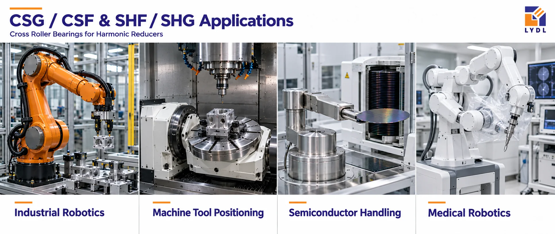
Industrial-robot applications can include a small gripper orienting axis, where the tool offset and hose forces need review. A machine-tool accessory might use a compact actuator for positioning a probe or attachment rather than carrying an unspecified cutting load. Semiconductor equipment can use similar output support in articulated inspection mechanisms, with cleanliness handled separately. Medical positioning equipment may use a compact joint only after its full device requirements are evaluated.
Illustrated fields require model-specific interface and environmental review.
For size 17, useful inspection records distinguish the 10 mm bore from the reducer size number and identify all critical flange features. Include drawing revision, seating diameters and the agreed rotational checks. Discuss what can be reported for each delivery and how the bearing will be marked. See LYDL company and manufacturing information for the supplier background before arranging a technical review.
Specify individual protection where several bearings are shipped together. Keep machined faces separated from cartons, tools and spare bolts that could scratch them. Record any storage or handling instructions supplied with the order. A representative packaging image may explain the protection method, but an order's inspection and packing requirements should still be stated in its commercial documents.

The number 17 is a reducer-family size designation rather than a bore code. The LYDL dimensional reference lists d = 10 mm. Use the numerical drawing dimensions when matching the shaft, register and available installation space.
M5 identifies the nominal thread, not its usable engagement depth or clearance beyond the hole. The model drawing and mating flange must establish bolt length, head access and tightening requirements. Check possible interference with moving components.
Record the travel direction, working load, tool position and measurement point. Separate the bearing-related rotational checks from commanded-position accuracy of the complete actuator. Include the mounting state so repeated test results can be compared meaningfully.
No. H, C, B and H2 identify different section features. Read their locations on the drawing and confirm the seat stack-up. Combining them as if they all described the overall bearing width would misrepresent the interface.
Provide starting and running conditions, temperature, seal arrangement and movement pattern. Explain whether the value is measured on the loose bearing or installed actuator. A single torque reading without those details may not identify the required component behaviour.
Use LYDL technical enquiry to submit the size-17 assembly section, fastening access and repetition-test requirements. Add the full reducer reference, operating cycle and purchase quantity. LYDL can then review the specified interfaces and acceptance measurements together.
LYDL supplies its own bearings. Referenced brand names identify comparison families; agreed drawings and order specifications define supplied performance.