

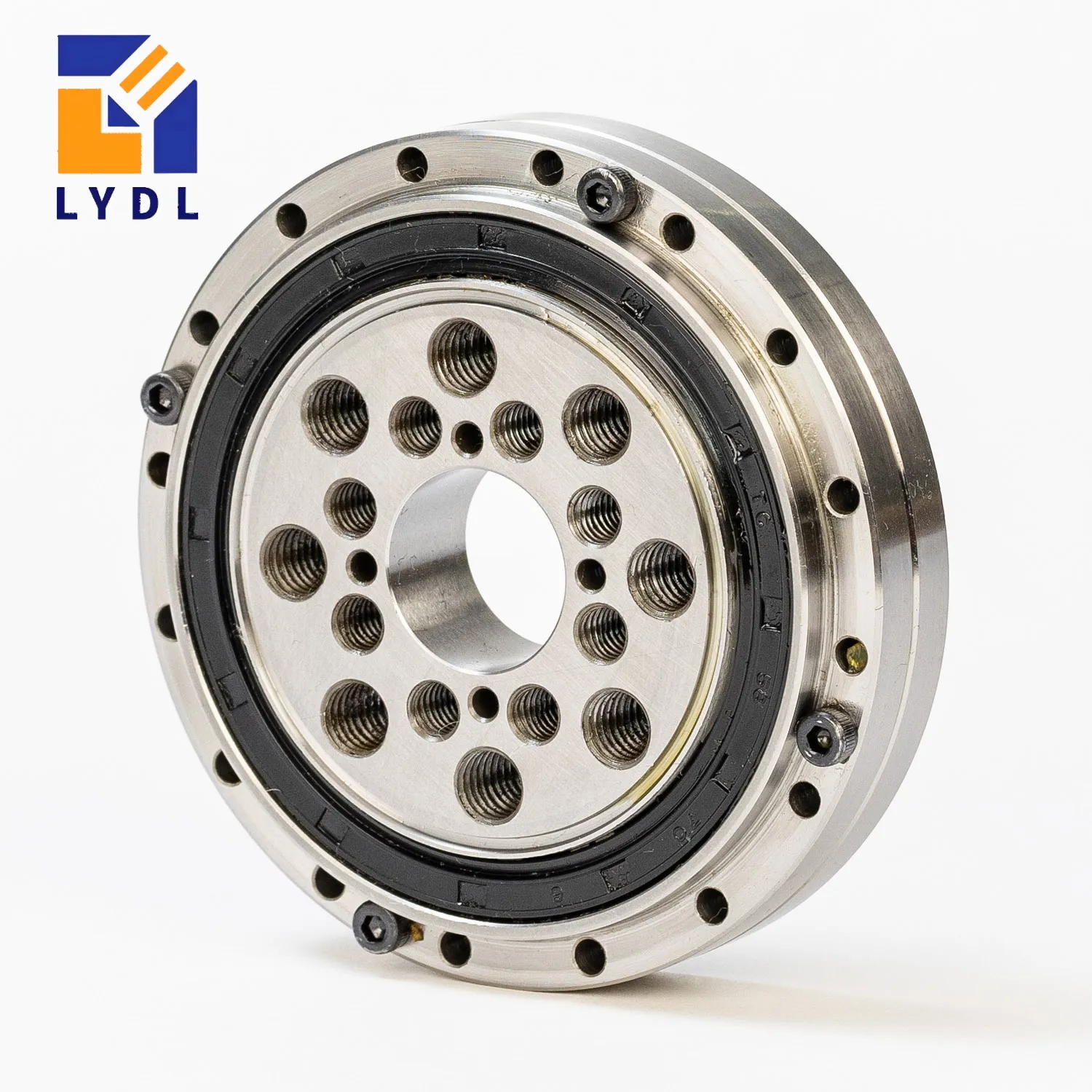
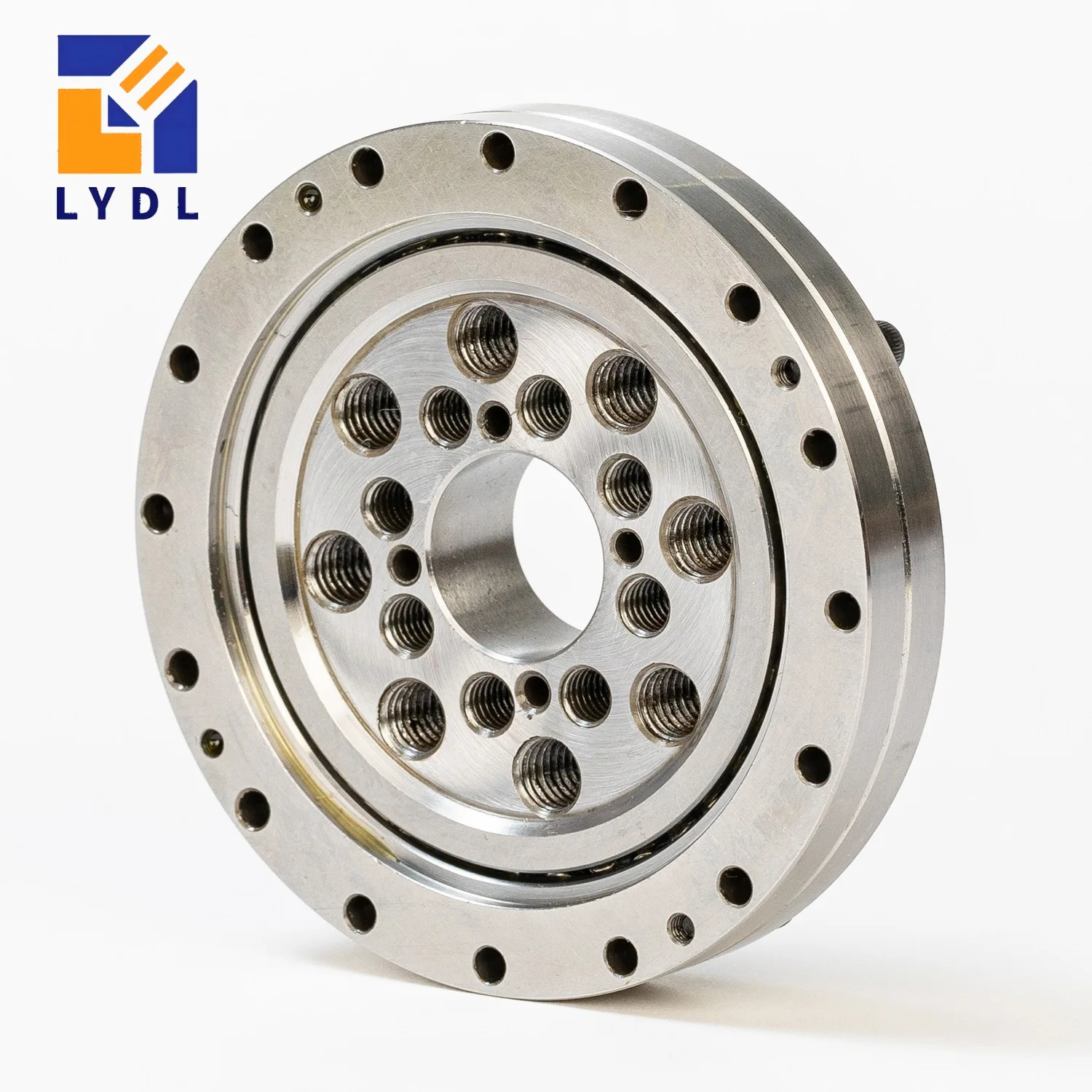
CSG-14 / CSF-14 cross roller bearing selection starts with the small flange interfaces, not simply the size-14 reducer label. The LYDL reference has a 55 mm outside diameter and 16.5 mm overall height, with alternative bore entries of 11 and 9 mm.
Compare this model with the CSG / CSF selection guide before confirming the interface.
The 11(9) entry deserves attention at the beginning of a replacement enquiry. It records two source-table alternatives; it does not describe a bore that may vary freely between those values. Ask which reducer configuration and drawing revision correspond to your existing assembly. The alternative 17(14.5) mm additional pitch circle and M4(M3) thread notation also require a matched drawing. Do not select each value independently to create an unverified combination.
Measure the shaft, locating recess and axial space; photograph both faces before dismantling.
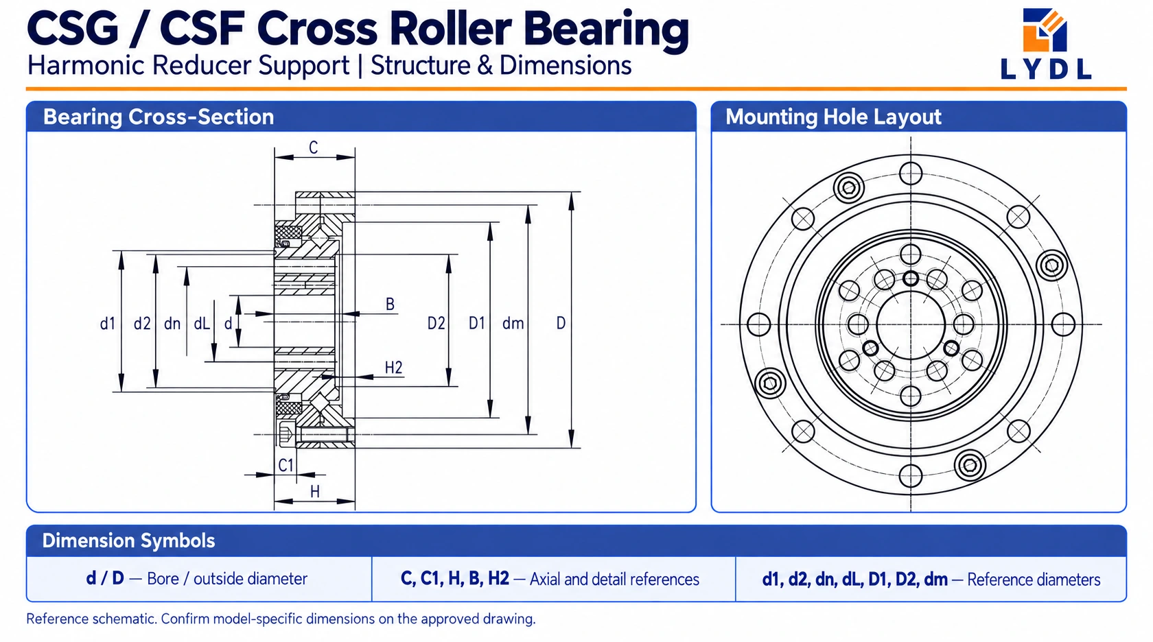
The structure diagram identifies the central diameter d, outer diameter D and overall axial dimension H. Its C, B and H2 symbols describe additional axial features. D1, D2, d1 and d2 locate secondary diameters; dm, dn and dL identify mounting circles. On this reference, the outer interface lists eight 3.5 mm holes on dm = 49 mm, while the inner interface lists six M4 holes on dn = 23 mm.
Inspect the hole positions and access for the intended fasteners on the model drawing. A plan-view illustration is useful for understanding the arrangement, but it should not replace a dimensioned manufacturing drawing. In particular, thread engagement and the depth available behind the flange need verification. The CSG / CSF bearing category groups this construction with related size references without implying that every listed interface is interchangeable.
| Reference feature | Value |
|---|---|
| d (mm) | 11(9) |
| D (mm) | 55 |
| H (mm) | 16.5 |
| C (mm) | 16 |
| B (mm) | 13.5 |
| H2 (mm) | 2.5 |
| D1 (mm) | 41.8 |
| D2 (mm) | 28 |
| d1 (mm) | 29.8 |
| d2 (mm) | 28.4 |
| Outer PCD dm (mm) | 49 |
| Outer fixing holes | 8-Φ3.5 |
| Inner PCD dn (mm) | 23 |
| Inner fixing holes | 6-M4 |
| Additional PCD dL (mm) | 17(14.5) |
| Additional fixing holes | 6-M4(M3) |
Dimensions: existing LYDL selection reference. The approved model drawing defines tolerances, variant mapping and supplied interfaces.
A small instrument can produce a relevant overturning moment when its sensor, bracket or cable support extends away from the bearing. Draw the output flange and mark the centre of gravity in the operating orientations. Identify radial and axial force components, then include acceleration and any contact force from the working tool. A mass figure without its location is insufficient for checking the support position.
For a camera head or inspection probe, the direction of the lever arm may change as the axis rotates. Review the demanding position rather than only the parked arrangement. Treat any simple force-times-distance calculation as a geometry check, not a complete capacity assessment. The original gear-unit data below provides context; the supplied LYDL bearing needs its own confirmed rating and operating assumptions.
Instrument positioning often makes low starting resistance and stable flange behaviour important. State the travel angle, reversal frequency, speed and required runout at the mounting face. Explain whether acceptance is measured on the loose bearing or after installation. These are different conditions: the housing and bolts can influence the mounted result.
Do not infer a bearing precision grade from the original reducer's positioning-accuracy statement. Likewise, a zero-backlash gear-unit description does not establish zero clearance in a replacement support bearing. Agree clearance or preload, running torque, seals and lubricant in the order specification. Where a different support construction is possible, use the LYDL cross roller bearing range to compare interfaces and space requirements before changing the surrounding mechanism.
| Reference feature | Value |
|---|---|
| Basic dynamic load C (kN) | 4.74 |
| Basic static load C0 (kN) | 6.07 |
| Catalogue moment Mc (Nm) | 41 |
Harmonic Drive catalogue, printed page 33, Table 30. Source load units ×10² N converted to kN. Confirm configuration and rated conditions before calculation.
Small fasteners and narrow seating areas make careful preparation worthwhile. Clean the flange recess and remove raised edges that prevent even seating. Confirm that the bearing is supported by the intended shoulder rather than an incidental edge. Tighten the agreed fasteners using the installation sequence and torque specified for the assembly; hole diameter alone is not enough to determine a tightening value.
Check free movement before and after clamping, then record the mounted runout where the instrument attaches. If resistance changes after tightening, investigate seating, alignment and bolt interference before operating the mechanism. Avoid using fasteners to pull a visibly misaligned component into position. An inspection record is more useful when it identifies the measurement location and the installed condition rather than reporting only a general pass result.
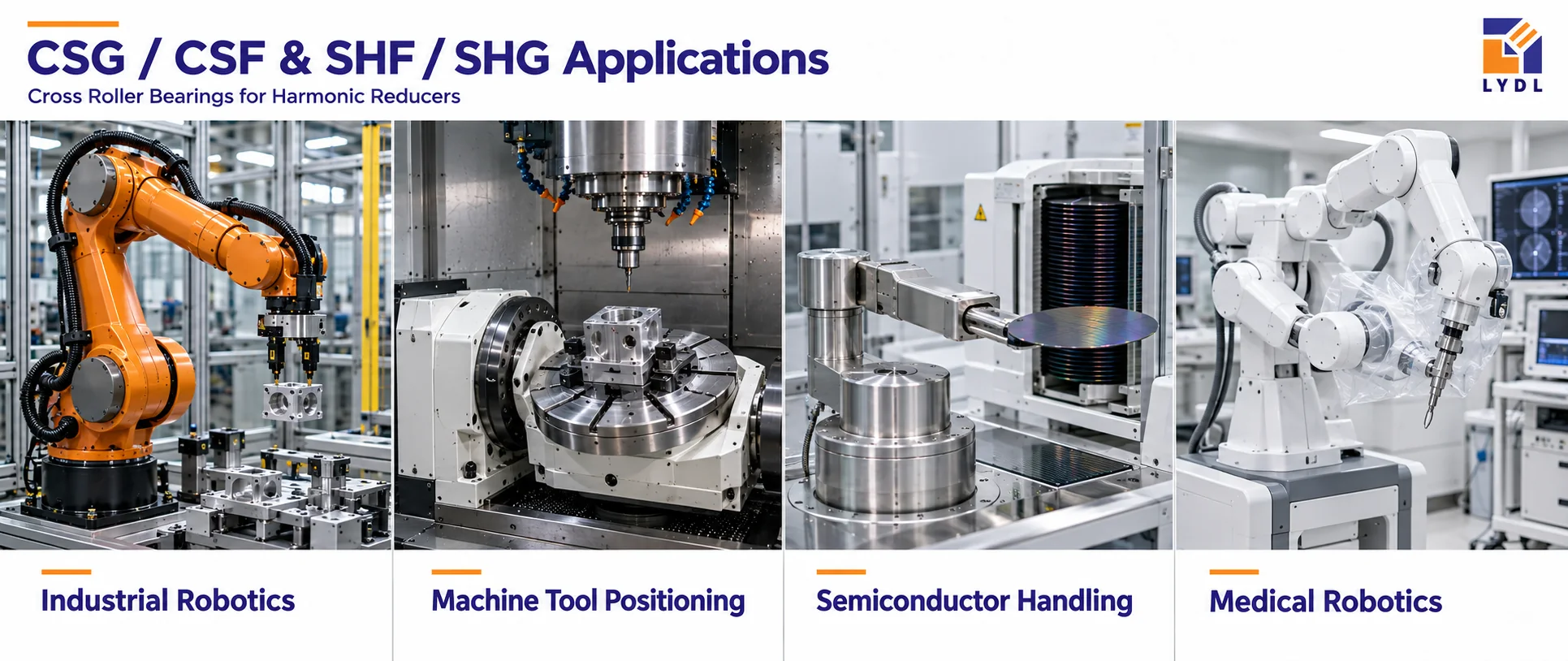
The shared application graphic illustrates four equipment fields rather than documented installations of this exact size. In industrial robotics, size-14 review may concern a compact wrist or end-effector orientation flange. In machine-tool positioning, consider a small orienting attachment only after checking its process forces. Semiconductor handling may involve an inspection or transfer-head axis, with separate cleanliness requirements. Medical robotics may involve a small articulated positioning stage, subject to the complete device's engineering validation.
These examples help identify the bearing's mechanical role. They do not determine permissible payload, certify cleanroom use or establish compatibility with a particular machine.
Before shipment, agree which characteristics matter to the assembly: the selected bore, locating steps, hole interfaces, axial dimensions and specified rotational checks. Ask for the part identification and drawing revision on the report. For repeated purchases, retain the approved reference so that a later order does not accidentally switch the bore or fixing variant. The LYDL company and manufacturing information provides company context for the enquiry.
Discuss corrosion protection and individual separation during transport. Protect the machined faces and keep loose hardware from contacting the bearing. Packaging photographs should show the actual arrangement or be clearly identified as representative. The proposed inspection image is intended to accompany confirmed checks, not to stand in for a model-specific inspection report.

Both entries appear in the LYDL reference as alternatives. Select the value associated with your complete reducer and approved bearing drawing. The notation is not a tolerance and does not authorise machining the bore to an arbitrary intermediate diameter.
The source contains an alternative thread entry, but its configuration mapping is not established by the table. Request the drawing that ties the bore, pitch circle and thread together. Verify thread depth and mating fasteners on that version.
Include the bracket and cable forces, the distance from the support, motion acceleration and operating orientation. A light payload at a long offset can create a different support requirement from the same weight mounted close to the flange.
Specify the bearing and mounted flange measurements separately. Reducer positioning accuracy concerns the complete transmission. State the required runout, running behaviour and measurement conditions so the component acceptance criteria address the actual instrument mounting.
Provide both bearing faces, the housing seat, driven flange and original fastener arrangement. Include measured bore, outside diameter and axial steps. A scale in the photograph is helpful, but measured dimensions and a controlled drawing remain necessary.
Send the selected bore variant, both flange views and your instrument load arrangement through LYDL technical enquiry. Include quantity, the complete reducer identification and the required mounted checks so LYDL can review the size-14 interface before quotation.
LYDL supplies its own bearings. Referenced brand names identify comparison families; agreed drawings and order specifications define supplied performance.