

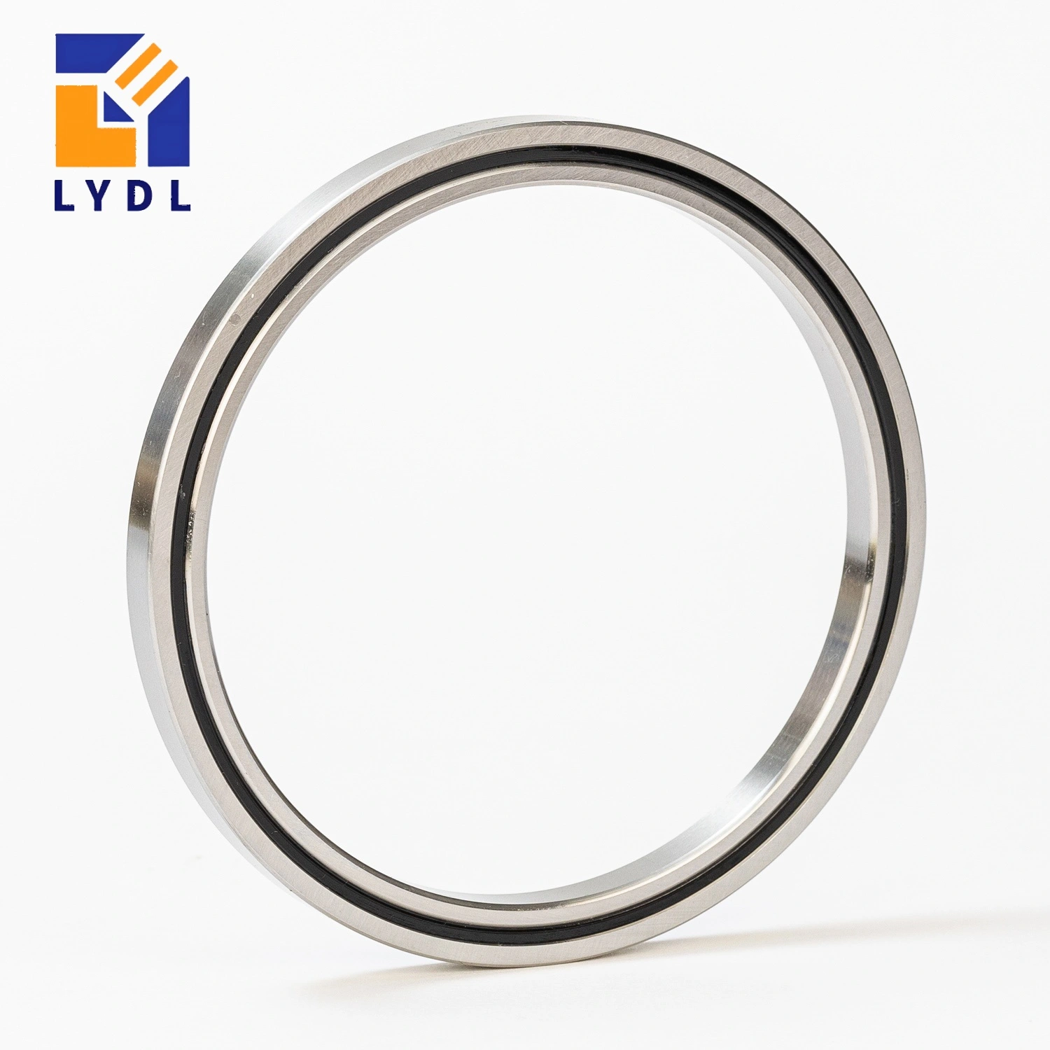
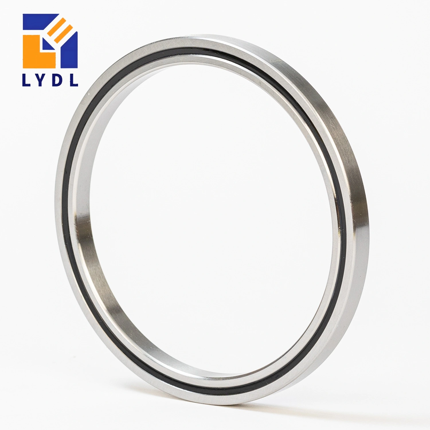
The RAU8005C0 cross roller bearing reference has an 80 × 91 × 5 mm envelope. It can be evaluated for a shallow sample carrier, inspection swivel or compact positioning assembly that needs an annular hub. THK defines the standard thin reference as open, with C0 clearance and normal grade 0 accuracy. The 5 mm width belongs to the bearing component, not the whole carrier mechanism. [3, 4]
Start with the cross roller bearing selection guide and the actual carrier layout. THK documents the RAU8005 reference, while the reviewed IKO standard CRBT range does not establish an 80 mm counterpart. Include the original full designation and supplier drawing in a replacement enquiry so clearance, accuracy and lubrication can be compared along with nominal size. [2, 3]
| Parameter | THK RAU8005C0 |
|---|---|
| Bore d | 80 mm |
| Outside diameter D | 91 mm |
| Width B / B1 | 5 mm |
| Radial section (D – d) / 2 | 5.5 mm |
| Roller pitch circle dp | 84.7 mm |
| Minimum chamfer r | 0.15 mm |
| Shaft shoulder ds (maximum) | 82.5 mm |
| Housing shoulder Dh (minimum) | 87 mm |
| Dynamic radial load rating C | 3.05 kN |
| Static radial load rating C0 | 5.43 kN |
| Reference mass | 50 g |
| Lubrication holes | 2 x Ø1 mm |
| Reference seals | Open; seals not supported |
| Reference clearance / accuracy | C0 / normal grade 0 |
THK publishes dynamic radial C 3.05 kN, static radial C0 5.43 kN and a reference mass of 50 g. A sample carrier may experience changing mass distribution, acceleration and stationary process contact. Assess those conditions with their force directions and offsets rather than converting a radial rating into a general sample-weight limit. The catalogue is the stated technical reference; actual LYDL configuration and acceptance belong on the approved supply drawing. [3, 6]
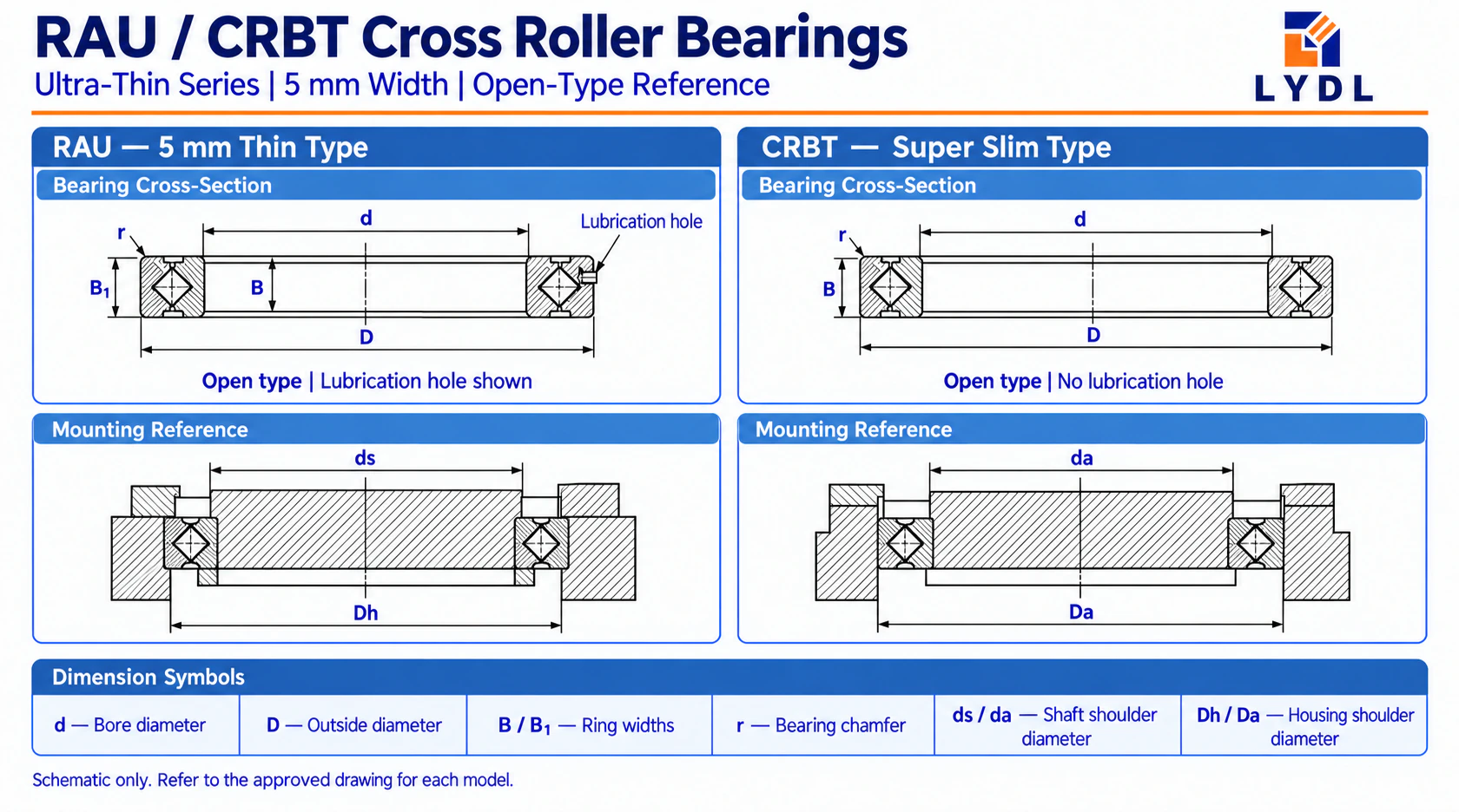
For the RAU panel, d = 80 mm, D = 91 mm and B/B1 = 5 mm. The roller pitch circle dp is 84.7 mm, with two Ø1 mm lubrication holes and a 0.15 mm minimum chamfer reference. THK specifies ds maximum 82.5 mm and Dh minimum 87 mm. The diagram’s CRBT panel illustrates separate oil-feature details and should not be interpreted as proof of a standard CRBT805A model. [2, 3]
A balanced empty carrier is only one operating state. Record the sample positions, maximum number installed and plausible uneven occupancy. A sample at the outside edge has a different lever arm from the same mass near the axis. Add any probe contact or clamping force that acts during the cycle, and identify whether it occurs in motion or at dwell.
The CRBT / RAU ultra-thin bearing range provides other 5 mm bore sizes for layout comparison. For the 80 mm option, include the carrier support annulus and any openings used for samples or services. A wide platform can impose an offset load on a narrow bearing section. Evaluate the supporting hub and retaining flange alongside the bearing instead of treating the nominal bore as a stability guarantee.
The official 5 mm RAU reference does not list P5 or seals; its standard choices are normal grade 0 and C0 clearance. If the laboratory or inspection process needs particular runout or tilt limits, write the measurement conditions and numerical acceptance. Distinguish the requirement on the supplied bearing from the performance of the completed sample carrier. [3]
Compare the RAU series size range for a wider assembly. RAU8008 has an 80 × 96 × 8 mm reference envelope, whereas RAU8005 uses 80 × 91 × 5 mm. Their housing seats, axial stack and shoulder references differ. A same-bore alternative therefore requires a complete interface check, especially if the existing carrier fixes its retaining and cover geometry.
A slow indexing axis can spend most of its cycle stationary. During that dwell, a probe, clamp or transfer mechanism may create the largest external load. Specify the direction, point of application and duration of that action. Cycle frequency alone does not reveal it, and an unloaded positioning check cannot establish behaviour during a process contact.
The CRBH / CRBHV bearing options may be considered when a larger construction is acceptable. Use the same carrier states and datum in the comparison so a design change can be assessed consistently. The proposal should explain its seat requirements and reference data. Preserve the process-load description even if the alternative has a substantially higher catalogue radial rating.
Use ds ≤ 82.5 mm and Dh ≥ 87 mm as THK support references. Define actual bearing fits and face alignment separately on the agreed drawing. Check mating corners around the 0.15 mm minimum chamfer reference. Show which flange establishes retention and which surface locates the carrier so the platform is not aligned against a temporary assembly condition. [3, 5]
Preserve access to the two Ø1 mm lubrication holes identified by the RAU reference. Coordinate the feed arrangement with covers, sample positions and cleaning paths. An open bearing may need an assembly enclosure suited to the stated exposure. That enclosure is a separate protection feature and should not be represented as an integral standard bearing seal.
Measure the relevant carrier datum after retention and after installing the remaining parts. Repeat the motion check with representative loading and agreed sample positions. If acceptance includes a dwell contact, reproduce that condition using the defined method. Keep bearing-level inspection and assembly validation distinguishable so a change in one can be interpreted correctly.
For bearing acceptance, identify dimensions, clearance and inspection datums. A supplied carrier needs separately stated test radius, sample pattern and process condition.
Protect the open bearing and label the 80 × 91 × 5 mm envelope to distinguish wider alternatives. Agree packing support, corrosion protection and traceability. The montage describes methods; request actual reports for order-specific evidence.

The mass distribution and resulting moment can differ from those of a full or empty balanced carrier. Specify where samples may be present and their offsets. Include realistic uneven states in the review rather than representing the load only by one total mass.
Not directly. THK’s C and C0 figures are radial bearing ratings. Sample position, process contact and the assembly’s force directions affect the selection calculation. State the actual geometry and duty before defining an allowable carrier load. [3, 6]
The bore is common, but RAU8005 measures 80 × 91 × 5 mm and RAU8008 measures 80 × 96 × 8 mm. Their housing and support details must be checked separately. A shared shaft diameter does not make the wider assembly interfaces identical.
Describe any clamp, probe or transfer force present during dwell, including direction and offset. Also state how often the condition occurs. The highest external load may happen while the axis is stopped, so cycle speed alone is insufficient.
No such model was identified in the official CRBT sources reviewed. THK’s RAU8005 row supplies the verified reference here. Evaluate any custom counterpart from its controlled drawing, clearance, lubricant features and actual ratings rather than extrapolating the standard IKO model range. [2, 3]
Send the carrier section, possible sample patterns, process forces and cycle timing. Reference RAU8005C0 and separate bare-bearing from carrier-level acceptance. You can contact LYDL to review the required LYDL configuration, numerical inspection limits and export protection using the actual loaded and stationary conditions.
Reference review: 10 October 2026. Brand names identify technical sources, not LYDL affiliation. The agreed LYDL drawing and quotation define supply.