

The CRBT155A cross roller bearing reference has a 15 × 26 × 5 mm envelope. THK RAU1505C0 shares those nominal dimensions, allowing a useful size comparison while the two source specifications remain distinct. Both references are open types. This compact section can be evaluated for a small sensor pivot or instrument joint, provided its surrounding support and duty are reviewed. [1, 3]
For a sensor axis, the essential dimension may be the distance from the bearing to the sensing surface. The bearing seat alone does not define pointing performance. Use the cross roller bearing selection guide to select the construction, then show the sensor bracket, actuator attachment and cable route on the mechanism section.
| Parameter | IKO CRBT155A | THK RAU1505C0 |
|---|---|---|
| Bore d | 15 mm | 15 mm |
| Outside diameter D | 26 mm | 26 mm |
| Width (IKO B / THK B, B1) | 5 mm | 5 mm |
| Radial section (D – d) / 2 | 5.5 mm | 5.5 mm |
| Roller pitch circle dp | Not stated in cited IKO row | 19.7 mm |
| Minimum chamfer r | 0.15 mm | 0.15 mm |
| Shoulder (IKO da / THK ds max) | 17.5 mm | 17.5 mm |
| Shoulder (IKO Da / THK Dh min) | 22 mm | 22 mm |
| Dynamic radial load rating C | 1.32 kN | 1.32 kN |
| Static radial load rating C0 | 1.110 kN | 1.10 kN |
| Reference mass | 11.9 g | 12 g |
| Lubrication holes | None in standard CRBT…A | 2 x Ø1 mm |
| Reference seals | Open type | Open; seals not supported |
| Reference clearance / accuracy | C1 / normal grade 0 | C0 / normal grade 0 |
C is 1.32 kN in both cited model rows. IKO lists C0 as 1.110 kN and mass as 11.9 g; THK lists C0 as 1.10 kN and mass as 12 g. These small published differences should remain attributed. The radial ratings do not state allowable sensor overhang or a complete positioning error. Supply load locations and operating cycle for selection, with actual LYDL acceptance data established by the order specification. [1, 3, 6]
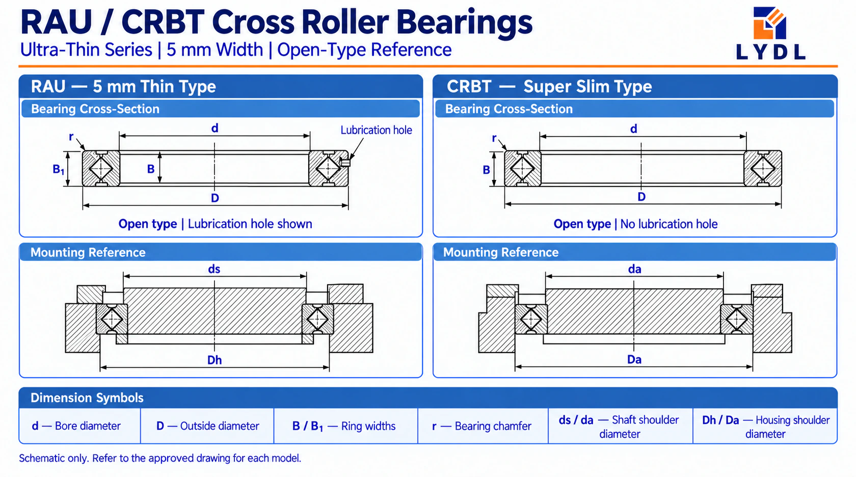
The 15 mm bore is d, 26 mm outside diameter is D and axial width is 5 mm. THK’s roller pitch circle reference is 19.7 mm. Supporting shoulders use THK ds maximum 17.5 mm and Dh minimum 22 mm; IKO shows da/Da mounting references. The RAU panel includes lubricant access, whereas standard CRBT155A has no oil hole. Neither panel is a fabrication drawing or a bearing mounting-bolt layout. [1, 3]
A lightweight sensor can still load its pivot through an offset bracket. State the bracket length, sensor mass and any connector force applied during operation. Include the cable’s movement range and whether it bends around the pivot. A stiff cable can contribute to rotation resistance and pointing behaviour, so it belongs in the mechanism review.
Compare the CRBT / RAU ultra-thin bearing range for nearby bores if the sensor hub is not yet fixed. A 15 mm shaft seat should be chosen together with its wall, fasteners and service opening. Leave a practical route for installing the sensor and inspecting the axis. Compact bearings are useful when the complete module also preserves assembly and adjustment access.
IKO’s standard CRBT reference uses C1 clearance and normal-grade accuracy; the cited applicability table does not list P5. THK’s 5 mm RAU1505 reference is limited to C0 and normal grade 0, with no seal option. These manufacturer baselines are retained separately. A custom LYDL accuracy request should state allowed runout, dimensions and inspection datums rather than append an unverified P5 suffix. [2, 3]
The RAU series size range covers the separate wider RA-compatible group, whose suffix choices cannot be borrowed for this small 5 mm model. If replacing an existing sensor pivot, supply its complete designation and the original assembly drawing. Clearance codes from different brands need interpretation through their actual specifications, not a one-character substitution.
Define whether pointing is measured at a sensor housing, optical line or calibration target. The position of that reference changes how bracket deflection and bearing movement appear in the result. Keep the calibration process and measurement distance recorded. A nominal bearing precision term does not explain the resulting accuracy of an offset sensor module.
Consider the CRBH / CRBHV bearing options if more support space is available. Include the sensor offset and datum when evaluating an alternative construction and its mounting requirements.

Inspect the sensor hub and housing corners against the 0.15 mm minimum chamfer reference. Supporting shoulders must contact the intended ring faces without rubbing other components. Final fits depend on the actual reference design, loading and operating conditions. Do not infer a housing tolerance from the 22 mm shoulder dimension; it describes support geometry rather than the complete bearing seat. [1, 3, 5]
For an RAU-based supply, preserve access to the two Ø1 mm lubrication holes. For a standard CRBT-based supply, recognise that the reference has no oil hole and uses its own lubrication arrangement. Show the intended feature in the approved drawing so the module builder does not add a feed to the wrong configuration. Do not drill the bearing from the schematic.
Check rotation without the sensor cable, then with the cable connected. This comparison can identify external resistance that would otherwise be attributed to the bearing. Repeat the agreed reference-face measurement after retention, using the same datum. Include these steps in the module’s assembly instructions where cable reaction affects the useful sensing position.
Define ring inspection separately from sensor-pointing acceptance. State the numerical limits and measurement setup for each.
Protect the open bearing and its locating faces in individual packing. Identify the ordered configuration and requested reports. The generic montage illustrates inspection and export protection, rather than proof of a particular sensor-axis result.

No. Sensor bracket geometry, cable reaction, actuator behaviour and calibration also affect pointing. Specify the acceptance location and target distance. Bearing-ring runout should be recorded separately so a module-level requirement is not reduced to one component’s precision description.
Cable bending or tension can change rotation resistance and sensor position. Comparing the mechanism with and without the connected cable helps distinguish that effect. Record the routing and motion range so the final test represents normal use rather than an unloaded bare pivot.
They belong to separate IKO and THK model rows. IKO gives 11.9 g for CRBT155A, while THK gives 12 g for RAU1505. Keep each with its source; a shared nominal envelope does not require identical reference mass or internal geometry. [1, 3]
No. The cited 5 mm RAU catalogue specifies no seals, C0 clearance and normal grade 0 only. The wider RA-compatible family has different configuration choices. Do not transfer a UU image or wider-family suffix options to this miniature reference. [3]
It is THK’s minimum Dh support diameter for RAU1505, not the 26 mm bearing seat and not a complete fit tolerance. IKO uses a corresponding Da mounting symbol. Review the shoulder, locating seat and retaining face together on the approved assembly drawing. [1, 3]
Send the sensor bracket section, cable path, load offsets and pointing criterion for this 15 mm size. State the intended CRBT155A or RAU1505C0 reference and any separately required accuracy limits. You can contact LYDL with quantity and environmental conditions to obtain a clear LYDL configuration proposal and inspection agreement.
Reference review: 10 October 2026. Brand names identify technical sources, not LYDL affiliation. The agreed LYDL drawing and quotation define supply.