

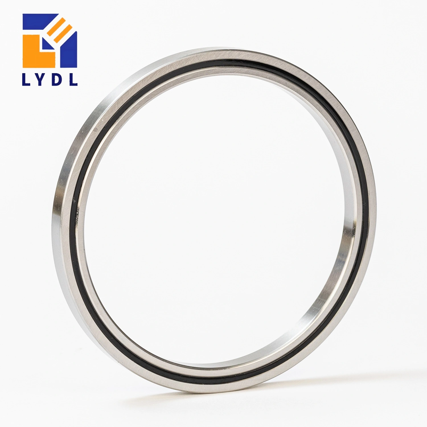
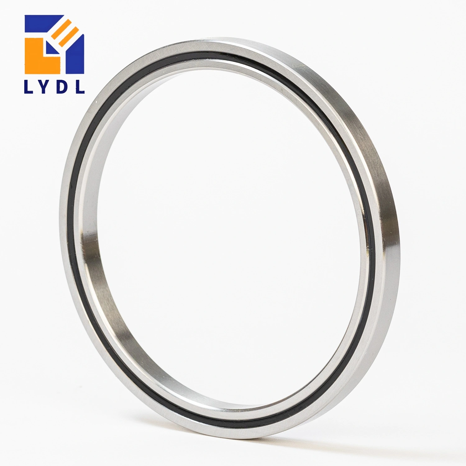
The RAU16013 cross roller bearing uses a 160 mm bore, 186 mm outside diameter and 13 mm width. It is a larger-section member of THK’s RA-compatible RAU range, with integral reference rings and suitability for evaluating either ring rotation. The 13 mm width and radial section distinguish it from the nearby 8 mm models. [1, 2]
For a rotary fixture or instrument platform, this envelope should be considered with the supporting shaft, housing and flange. A bearing section change alters the surrounding assembly and its installation height. Use the cross roller bearing selection guide to select a construction and retaining approach before assigning performance to the finished platform.
| Parameter | THK RAU16013 |
|---|---|
| Bore d | 160 mm |
| Outside diameter D | 186 mm |
| Width B / B1 | 13 mm |
| Radial section (D – d) / 2 | 13 mm |
| Roller pitch circle dp | 172 mm |
| Minimum chamfer r | 0.8 mm |
| Shaft shoulder ds (maximum) | 165 mm |
| Housing shoulder Dh (minimum) | 179 mm |
| Dynamic radial load rating C | 23.30 kN |
| Static radial load rating C0 | 44.90 kN |
| Reference mass | 0.59 kg |
| Lubrication holes | 4 x Ø2 mm |
The THK reference ratings for RAU16013 are 23.30 kN dynamic radial and 44.90 kN static radial, with a mass reference of 0.59 kg. The step in catalogue ratings relative to an 8 mm model reflects a different model design; it is not a rule for multiplying capacity by width. Applied axial forces, offset moments and required service life need their own assessment. Keep LYDL supplied ratings tied to the approved specification. [2, 6]
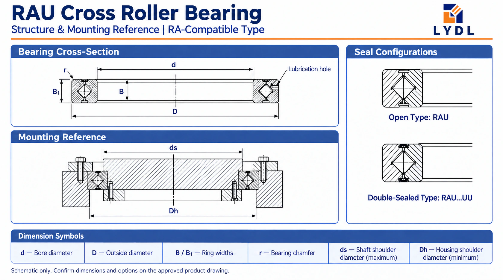
In the diagram, d = 160 mm, D = 186 mm and B/B1 = 13 mm. The roller pitch reference is 172 mm. Maximum shaft shoulder ds is 165 mm; minimum housing shoulder Dh is 179 mm. The reference chamfer minimum is 0.8 mm, and lubrication holes are Ø2 mm rather than the Ø1.5 mm openings of the narrower models. The schematic provides symbol meaning, while the actual drawing controls detailed geometry. [2]
Moving from RAU15008 to RAU16013 adds 10 mm of bore, 20 mm of outside diameter and 5 mm of width. Check the housing wall, flange height and drive alignment rather than treating this as a minor size increment. The assembly’s encoder and coupling may need repositioning when the axial reference changes.
The RAU series size range shows the range transition, which is useful when selecting a seat around an existing hub. Confirm every dimensional row for the chosen model. A shaft shoulder borrowed from an 8 mm reference can be inappropriate for the 13 mm section. Keep the selected bearing’s complete dimensional record attached to the shaft and housing design review.
Describe whether the hub or surrounding platform ring rotates, and identify the reference face whose runout matters. THK distinguishes seal arrangement, clearance or preload and accuracy grade. These should appear as separate agreed requirements in a LYDL order. Do not assume that an increase in section automatically sets a tighter tolerance or a specific preload. [3]
Consult the RA series comparison if the original mechanism uses a separable outer-ring reference. A dimensional comparison is helpful, but an integral-ring replacement still needs its retention, seal and lubrication interfaces checked. Supply the original full code and assembly drawing so the proposed configuration can be reviewed against more than the nominal 160 mm bore.
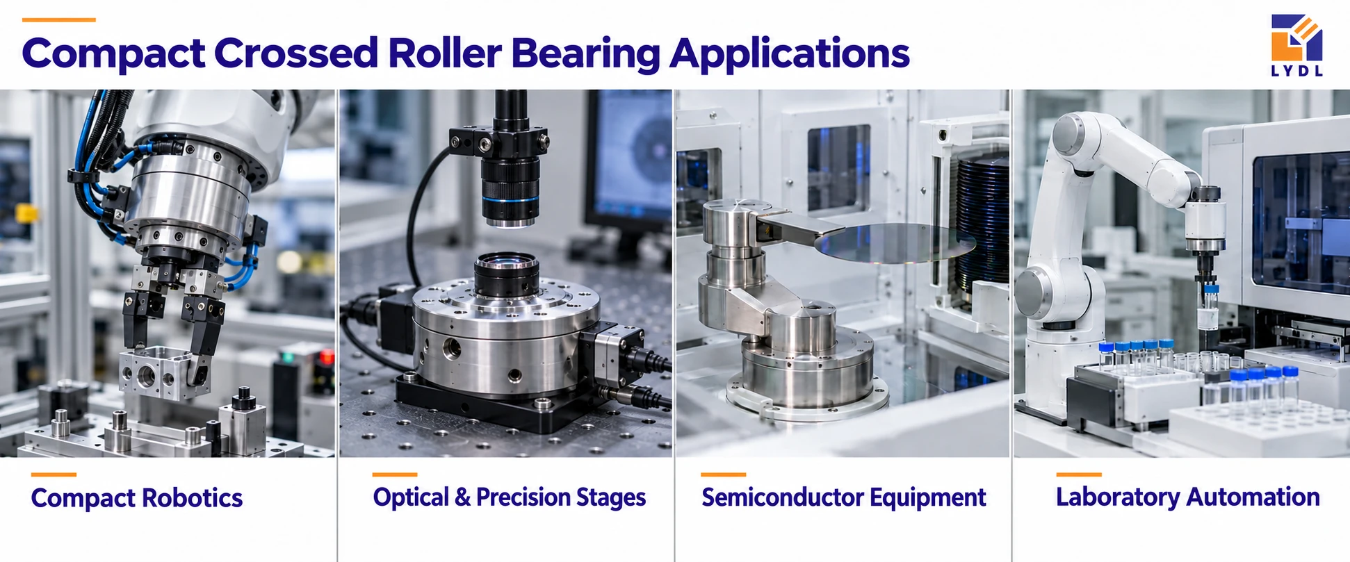
A fixture platform may experience a short process force at an offset location while the drive is holding position. Describe that condition separately from the normal moving cycle. Include force direction, application point and any impact. The static radial rating does not independently define an allowable process force at the platform rim.
Compare the CRBH / CRBHV bearing options for other available sections when the mechanism permits. Each option requires its own seat and support design. Evaluate the bearing, platform and drive together: a stiffer retained structure may be more valuable than an isolated catalogue-rating increase if the existing drive alignment or fixture plate remains the limiting interface.
Use the 165 mm maximum shaft shoulder and 179 mm minimum housing shoulder from the selected RAU16013 reference. Verify mating corners against the 0.8 mm minimum chamfer and the actual supplied profile. The larger section does not remove the need for accurate, clean support faces. Establish fits from the approved dimensions and operating conditions rather than using an assumed tolerance class. [2, 4]
The reference identifies four Ø2 mm lubrication holes. Reserve their access when designing a taller flange or repositioned drive. These holes remain lubricant features, not fastening locations. Check the insertion plug against the maximum-load region, including any fixed process-force direction, and mark the required orientation on the assembly record when it affects the design. [2, 5]
After seating, verify rotation before connecting the drive. Repeat the agreed runout checks after the retaining flange and platform are fitted. Only then align the coupling and encoder to the completed axis reference. This sequence helps avoid adjusting the drive to a temporary bearing position that later changes during final retention.
Specify 13 mm-width component geometry, selected clearance and rotating-ring inspection. Define drive-alignment and process-force tests separately for the assembled axis.
Support the bearing and protect its locating surfaces from loose fittings during shipment. Label the actual configuration and request agreed records. The inspection montage is an illustration, not a measurement certificate or confirmation of checks on each delivered unit.

It remains within the RA-compatible family but has a 13 mm width and radial section. Its seat, shoulder geometry, chamfer and lubricant-hole diameter differ from the 8 mm models. Review its own dimensional row rather than extending smaller-model details. [2]
No. Catalogue ratings belong to the individual bearing designs. Internal geometry and other design factors affect them. Use RAU16013’s published reference values for comparison, then assess combined loads and life using the actual operating conditions. [2, 6]
The THK RAU16013 reference lists four Ø2 mm lubrication holes. Check their actual locations on the approved drawing and preserve access around the retained assembly. Do not use the narrower family’s Ø1.5 mm detail or treat the openings as fixing holes. [2]
The retaining flange and platform can influence the completed axis reference. Aligning a drive to a temporary seating condition may require rework after the full assembly is clamped. Confirm the retained-axis measurements first, then align the coupling and encoder to that reference.
No. A rim force creates moment according to its offset, and may combine with axial and radial loads. Specify the force direction and location, impact condition and required static margin. A complete assembly assessment is needed before stating an allowable process force. [6]
For RAU16013, provide the platform section, drive alignment and all process-force locations. Include the moving cycle and held-load conditions separately. You can contact LYDL with the rotating-ring requirement, quantity and full existing code. Request a reviewed dimensional drawing and agreed bearing-level acceptance before releasing the larger-section installation.
Reference review: 10 October 2026. Brand names identify technical sources, not LYDL affiliation. The agreed LYDL drawing and quotation define supply.