

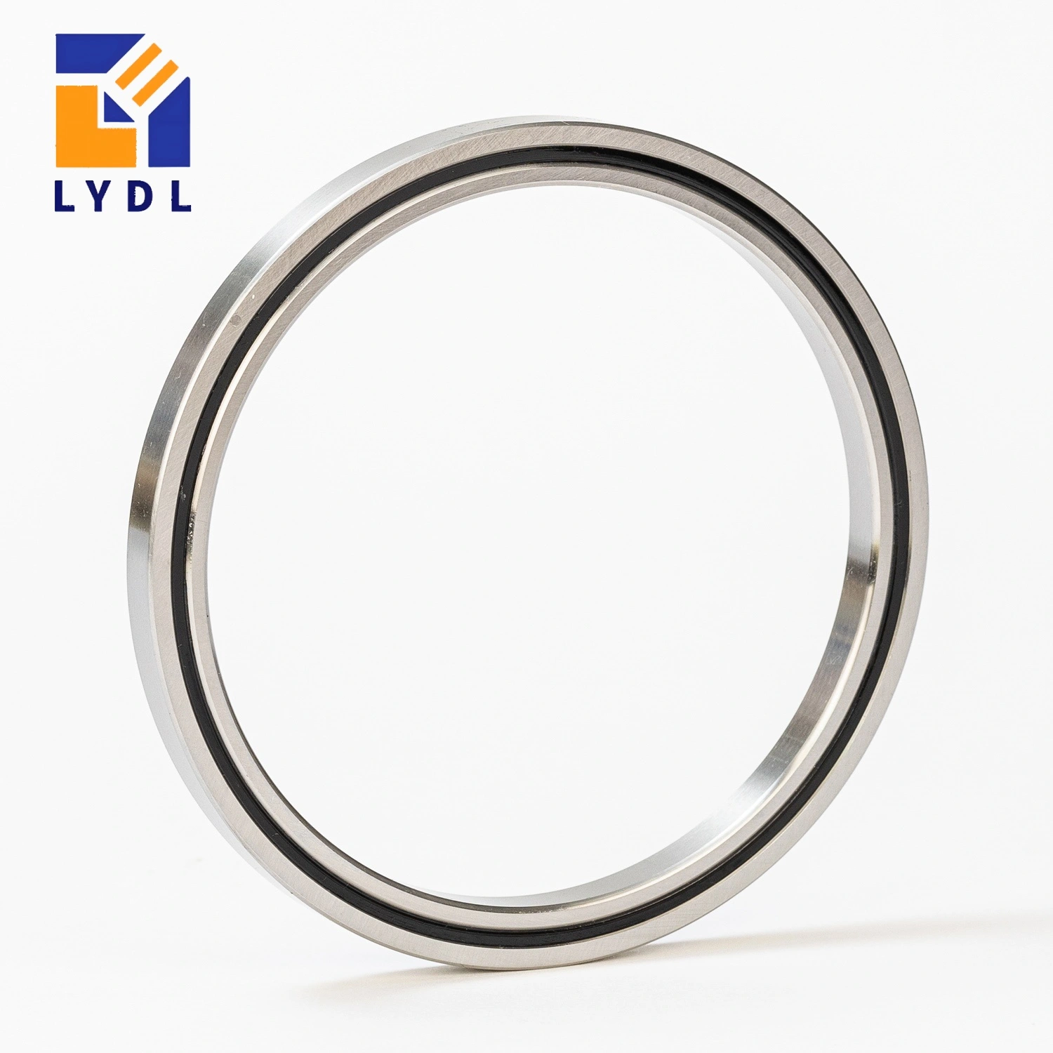
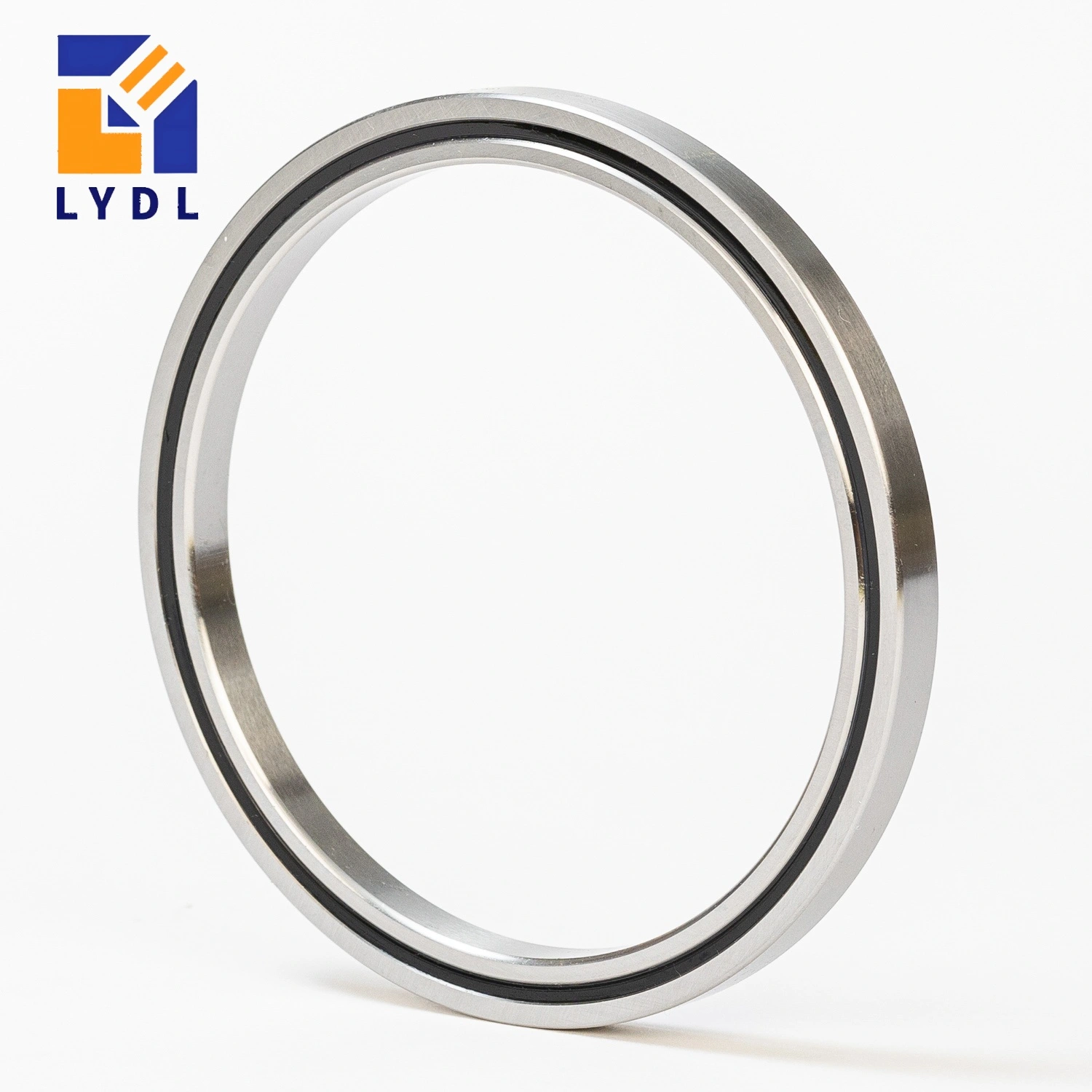
The RAU12008 cross roller bearing provides a 120 mm bore in a 136 mm outside diameter with an 8 mm width. The THK RA-compatible reference uses integral rings, with crossed rollers arranged to accommodate combined load directions within the rated design conditions. Its thin envelope suits layout studies where the rotating platform must remain low, but platform stiffness still needs an independent assessment. [1, 2]
A large central seat does not automatically make the surrounding platform rigid. The distance from the bearing to the working load, plate cut-outs and retention geometry determine how the load reaches the ring. Use the cross roller bearing selection guide to evaluate the complete bearing arrangement, then describe the actual platform rather than reducing the enquiry to its total weight.
| Parameter | THK RAU12008 |
|---|---|
| Bore d | 120 mm |
| Outside diameter D | 136 mm |
| Width B / B1 | 8 mm |
| Radial section (D – d) / 2 | 8 mm |
| Roller pitch circle dp | 127 mm |
| Minimum chamfer r | 0.5 mm |
| Shaft shoulder ds (maximum) | 123.5 mm |
| Housing shoulder Dh (minimum) | 130.5 mm |
| Dynamic radial load rating C | 7.84 kN |
| Static radial load rating C0 | 16.50 kN |
| Reference mass | 0.17 kg |
| Lubrication holes | 4 x Ø1.5 mm |
The published THK RAU12008 row specifies a dynamic radial rating of 7.84 kN, static radial rating of 16.50 kN and reference mass of 0.17 kg. Keep the radial nature of these ratings clear. A force acting far outside the ring produces an overturning moment, and a local process reaction may differ from the platform’s gravity load. Combined-load assessment and desired life are necessary before assigning a working capacity. [2, 6]
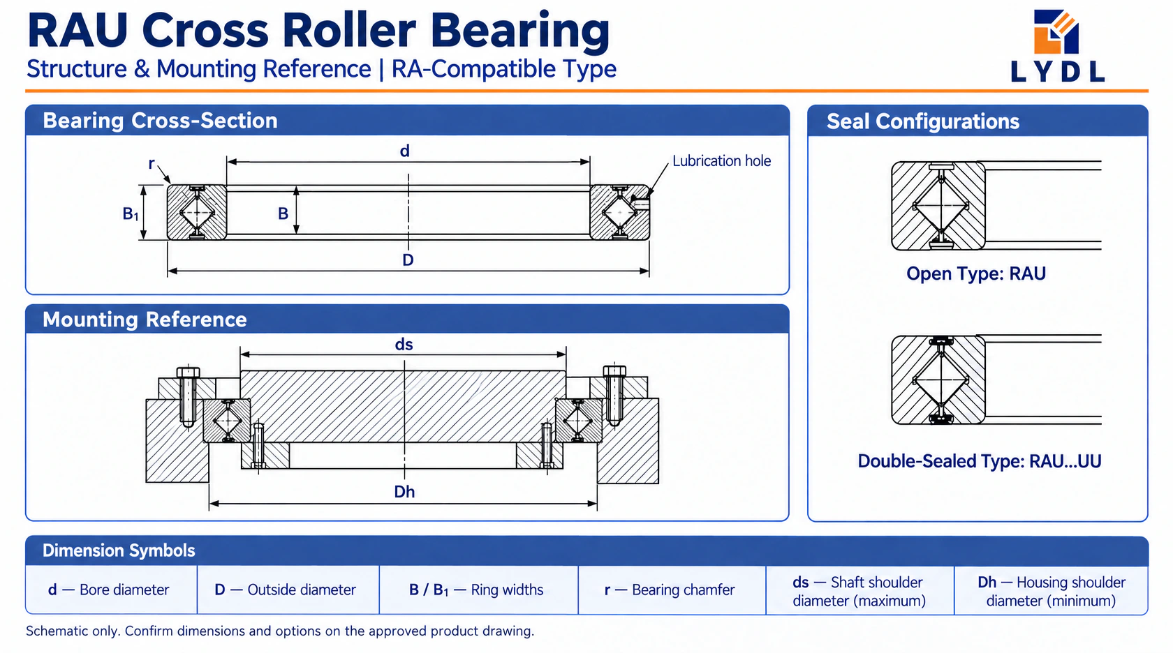
The schematic maps d to 120 mm, D to 136 mm and B/B1 to 8 mm. The internal roller pitch circle is 127 mm. For shoulder geometry, ds is a maximum of 123.5 mm and Dh is a minimum of 130.5 mm. Supporting components should follow those directions and the approved corner details. The small oil opening is not an attachment point for the platform, and the alternative seal sections do not specify a default LYDL configuration. [2]
Draw the platform and housing as load paths. Identify the region supporting the ring and the points where fixtures or process tools introduce force. Slots, cable openings and lightweight pockets can interrupt this path. Include them in the stiffness review instead of considering only a solid circular plate with the same outside diameter.
Neighbouring sizes in the RAU series size range can help when the hub diameter or service opening is still changing. RAU12008 is not a scaled-up assurance of every smaller model’s performance. Select its own reference row, seat and shoulder dimensions. Make enough room for flange installation and measurement access, especially when the top plate conceals most of the bearing after assembly.
Define runout at the ring and at the platform separately. The platform requirement should name its measurement radius and load state; the bearing requirement should identify the rotating ring and reference face. THK’s accuracy, clearance and seal codes describe independent attributes. For LYDL, put the agreed attributes and inspection method on the supply drawing so the delivered configuration is unambiguous. [3]
Use the RA series comparison when the machine currently retains a separable outer ring. A common 120 × 136 × 8 mm envelope can be useful during a retrofit, but clamp contact, insertion orientation and service access need verification. The integral RAU design should be evaluated against the complete original arrangement rather than against dimensions alone.
A runout value measured near the bearing is not the same acceptance statement as movement at the platform rim. Specify where the indicator or sensor contacts the rotating member and whether fixtures are installed. If loaded flatness or tilt affects the process, state the distribution of that load. The test must represent the operation it is intended to accept.
The CRBH / CRBHV bearing options offers other sections where a broader support envelope can be accommodated. Compare those candidates through their own dimensions, ratings and retaining systems. Increasing bearing section cannot correct an unsupported platform plate by itself. Retain the structural review as part of the decision rather than treating a catalogue rating as a substitute for assembly design.

Supporting shoulders use ds ≤ 123.5 mm and Dh ≥ 130.5 mm in the THK reference. Check that retaining parts contact the intended ring faces and leave appropriate corner clearance. Inspect the housing seat for unevenness and contamination before installation. A thin bearing can reflect distortion in the surrounding support, so control the assembly geometry as well as the bearing itself. [2, 4]
Four Ø1.5 mm lubrication holes are listed for this RAU reference. Locate the actual ports on the agreed drawing and arrange access around the platform’s frame. Keep these routes separate from fixing bolts and sensor brackets. Where a dominant moment direction exists, record the roller insertion plug orientation relative to the maximum-load zone in the assembly instructions. [2, 5]
Apply the approved retention sequence and recheck rotation as the assembly progresses. Compare measurements before and after fitting the broad platform plate. If a change follows clamping, inspect the support contact and plate condition before assuming that a different bearing grade will resolve it. Preserve this sequence for repeat builds and replacement maintenance.
Agree component measurements and the platform-level test radius separately. Record the relevant load condition, holding method and acceptance datum.
Use individual support and corrosion protection that preserve locating faces. Label the selected configuration and specify shipment records. The common montage explains inspection and export methods; receiving checks should use the approved requirements and identifiable supplied item.

No. The hub, top plate, housing and retaining flange all participate in the load path. Plate cut-outs and workpiece offsets can influence deflection. Review those features with the bearing selection instead of deriving platform stiffness from bore diameter alone.
The measurement location affects what movement is observed, especially when angular tilt is present. Name the radius, datum, fixture state and load condition. A number without that context cannot be reliably compared with a measurement taken close to the bearing ring.
No. It is THK’s static radial bearing rating. Platform loading also depends on axial forces, overturning moment, shock and the required safety factor. A working-load limit needs an approved assembly calculation and stated operating conditions. [2, 6]
Compare the assembly before and after plate retention, then inspect flange contact, locating faces, contamination and plate distortion. Check that external parts are not rubbing. A documented assembly sequence is more useful for diagnosis than an unexplained impression that the bearing feels tight.
Do not approve that replacement on the common envelope alone. The RA-compatible RAU reference has integral rings, whereas RA uses a separable outer ring. Match the full designation and examine clamp faces, seal arrangement and lubrication access against the original assembly. [1, 2]
Attach a platform section and plan with fixture positions, load offsets and support cut-outs. Name the runout test radius, rotating ring and intended duty. You can contact LYDL to review RAU12008 with quantity and configuration needs. Ask for model-specific drawing approval and clear separation of bearing acceptance from the assembled platform test.
Reference review: 10 October 2026. Brand names identify technical sources, not LYDL affiliation. The agreed LYDL drawing and quotation define supply.